Extron Electronics PowerCage FOX 3G HD-SDI Setup Guide User Manual
Powercage™ fox 3g hd-sdi • setup guide, Installation, Step 1 — install the board in the enclosure
This guide provides instructions for an experienced installer to set up and operate the Extron
®
PowerCage FOX 3G HD-SDI fiber optic video extender.
The PowerCage FOX 3G HD-SDI Fiber Optic Extender is a modular transceiver board for the
PowerCage 1600 enclosure, enabling long distance transmission of multi-rate SDI, HD-SDI, and
3G-SDI video signals, with embedded audio and metadata, over a fiber cable at rates of up to
2.97 Gbps. The PowerCage FOX 3G HD-SDI is compatible with the FOX 3G HD-SDI fiber optic
multi-rate SDI transceiver, the FOX 3G DVC, and the FOX series of distribution amplifiers and
switchers. It is available in singlemode and multimode configurations.
WARNING: This unit outputs continuous invisible light, which may be harmful to the eyes. For additional safety, plug the
attached dust caps into the optical transceivers when the fiber optic cable is unplugged.
NOTE: The PowerCage FOX 3G HD-SDI is a transceiver that can function as a transmitter, a receiver, or both. At least two boards
are required for a transmitter-receiver system, with at least one fiber optic cable linking each two units.
Installation
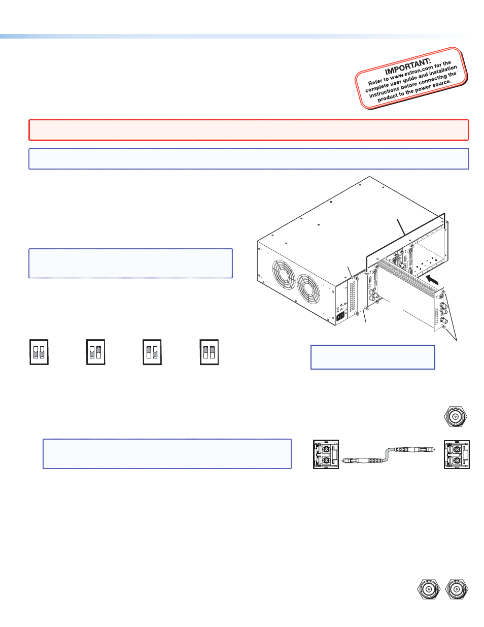
Step 1 — Install the Board in the Enclosure
Install the transceiver board in a PowerCage 1600 Enclosure slot, as
shown at right. Use a screwdriver or other tool to tighten the two
screws that hold the board in place.
NOTE: Ensure that the board is flush with the rear of
the enclosure and the that screws are tightened
securely before applying power.
Step 2 — Set the Mode DIP Switches
Set the rear panel Mode DIP switches to configure each unit that
will be installed in the system as a bidirectional transceiver, a
transmitter, or a receiver, as shown below.
Step 3 — Connect the Input, Output, and Fiber Cables
z
z
HD-SDI input connector — If the PowerCage FOX 3G HD-SDI is configured as either a bidirectional transceiver or
as a transmitter, connect an HD-SDI, SDI, or 3G-SDI video input to this BNC connector (shown at right).
z
z
Fiber optic connectors —
NOTE
: Ensure that you use the proper fiber cable for your transceivers.
Typically, singlemode fiber cable has a yellow jacket and
multimode fiber cable has an orange or aqua jacket.
z
z
Tx connector — In any configuration, connect a fiber optic cable to the optical Tx connector.
Connect the free end of this fiber optic cable to the optical Rx connector on another FOX 3G HD-SDI that is configured as a
bidirectional transceiver or as a receiver.
z
z
Rx connector — In either the bidirectional transceiver or receiver configuration, connect a fiber optic cable to the
optical Rx connector to receive the signal from the transmitting unit. Connect the free end to one of the following:
z
z
In a two-transceiver system, connect the free end of this cable to the optical Tx connector on the transmitting unit,
which is configured as a transmitter.
z
z
In a daisy-chained system, connect the free end of this cable to the optical Tx connector on the previous unit
in the daisy chain (configured as either a bidirectional transceiver or a transmitter).
z
z
HD/SDI output connectors — In any PowerCage FOX 3G HD-SDI configuration, connect a digital display
to these BNC connectors (shown at right).
HD/SDI INPUT
MODE
MODE
Bidirectional
Transceiver
1 down
2 down
1 down
2 up
Transmitter
1 2
1 2
MODE
1 up
2 down
Receiver with
Loop-through
1 2
MODE
1 up
2 up
Spare (receiver
with daisy-chaining)
1 2
Rx
Tx
Rx
Tx
HD/SDI OUTPUTS
1
2
R
E
M
O
TE
RS-232
RS-232
O
VER FIBE
R
T
x
R
x
Tx
A
LA
R
M
R
x
OUTPUT
R
G
B
Po
we
rCa
ge
FO
X 4G RX RG
B
T
x
R
x
L
R
A
U
D
IO
MONO
A
UDIO OUTPUT
1
2
SHARP
GAIN
Y/VID
C
INPUT
Po
we
rCa
ge
MTP R
AV
1
2
R
E
M
O
TE
RS-232
RS-232
O
VER FIBE
R
T
x
R
x
Tx
A
LA
R
M
R
x
OUTPUT
R
G
B
Po
we
rCa
ge
FO
X 4G RX RG
B
T
x
R
x
L
R
A
U
D
IO
5A MAX.
100-240
V 50/60H
z
N15
778
C
US
LIS
TED
1T2
3
I.T.
E.
1
2
REMO
TE
RS-232
RS-232
O
VER FIBE
R
Tx Rx
Tx
A
LA
R
M
Rx
VIDEO
1
2
3
4
Po
we
rCa
ge
FO
X 2G Rx
AV
Tx Rx
L
R
A
UDI
O
Align board
and slide
into slot.
Tx
Rx
HD/SDI INPUT
HD/SDI OUTPUT
S
MODE
Po
we
rCa
ge
FO
X 3G HD-SD
I
Screws
(2 per
board)
Power
Supply
Optional
Redundant Power
Supply Slot
16 Available Single Board
Slots (8 double board slots)
NOTE:
Power supplies can occupy only these
two power supply slots. (Each power
supply can be mounted in either slot.)
1
PowerCage™ FOX 3G HD-SDI • Setup Guide