Extron Electronics PowerCage FOX SR HDMI Setup Guide User Manual
Powercage fox sr hdmi • setup guide, Installation, Step 1 — mounting
PowerCage FOX SR HDMI • Setup Guide
This guide provides quick-start instructions for an experienced installer to set up and operate
the Extron PowerCage FOX SR HDMI scaling fiber optic receiver.
WARNING:
Risk of serious physical injury: The receiver outputs continuous
invisible light, which may be harmful to the eyes; use with caution.
For additional safety, plug the attached dust caps into the optical
transceivers when the fiber optic cable is unplugged
Installation
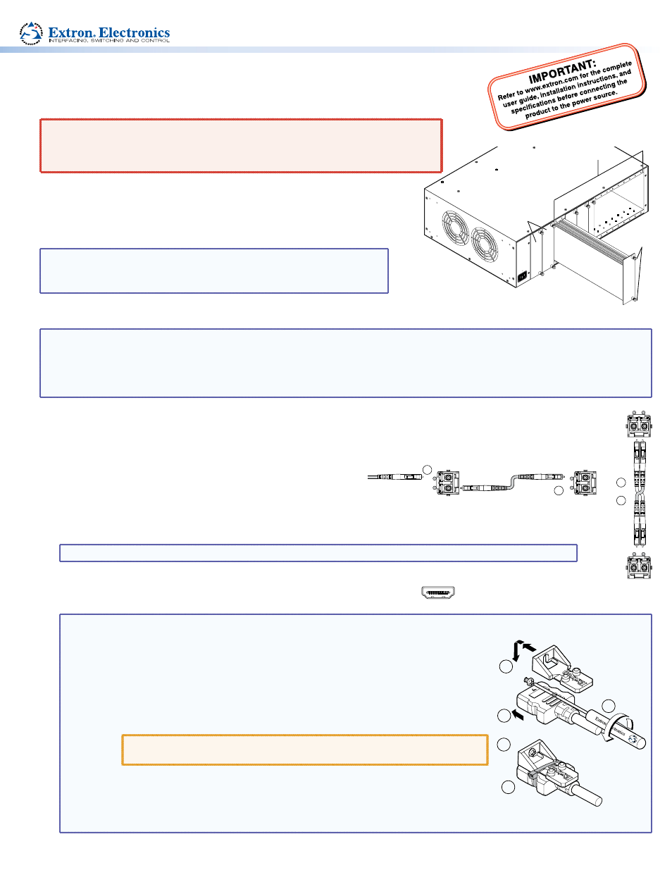
Step 1 — Mounting
Install the receiver into a PowerCage enclosure as required.
NOTES:
•
PowerCage boards are hot-swappable.
•
Ensure the boards are flush with the rear of the enclosure and
the screws are tightened securely before applying power.
Step 2 — Throughput Connections
NOTE: See the two fiber cable connection drawings below. You can connect the transmitter and one or more receivers in one of
three ways:
•
One way (transmitter to receiver) only, perform step 2a.
•
Two way (transmitter to receiver and return), perform steps 2a and 2b.
•
One way (transmitter to receiver) with daisy chain (receiver to receiver), perform steps 2a and 2c.
a.
Connect the fiber between the Tx port on the transmitter and the Rx port on the receiver.
b.
If you want the receiver to send return serial data (such as responses from a controlled device) to the transmitter,
connect a cable between the Tx port on the receiver and Rx port on the transmitter.
c.
If you want a receiver to daisy-chain the optical signal to
another receiver (up to 10 receivers in a daisy chain):
•
Connect the receiver Tx fiber cable to Rx on another receiver.
•
Set each receiver to daisy chain mode (see “
,” on the next page).
Tx Link and Rx Link LEDs — When lit, the link is active (light is output [Tx LED] or received [Rx LED]).
NOTE: The Link LEDs indicate transmission of light only, not whether there is data encoded in the optical link.
Step 3 — Output Connections
HDMI
a.
Connect an HDMI video display to the receiver HDMI Output connector.
NOTE: Use a LockIt™ Lacing Bracket to securely fasten an HDMI cable to the receiver as
follows.
1.
Plug the HDMI cable into the panel connection.
2.
Loosen the HDMI connection mounting screw from the panel enough to
allow the LockIt bracket to be placed over it. The screw does not have to be
removed.
3.
Place the LockIt lacing bracket on the screw and against the HDMI connector,
then tighten the screw to secure the bracket.
ATTENTION:
Do not overtighten the HDMI connector mounting screw.
The shield it fastens to is very thin and can easily be stripped.
4.
Loosely place the included tie wrap around the HDMI connector and the
LockIt lacing bracket as shown.
5.
While holding the connector securely against the lacing bracket, use pliers or
a similar tool to tighten the tie wrap, then remove any excess length.
3
3
1
2
4
5
5A MAX.
100-240V 50/60H
z
16 available single board slots or
8 double board slots
Power
Supply
Screws
Turn off or disconnect all equipment power
sources and mount the receiver as required.
Receiver
Transmitter
Tx
Rx
Tx
Rx
and
2a
2b
From Transmitter
or Daisy-Chained
Receiver
Receiver
Receiver
Tx
Rx
Tx
Rx
2a
2c