Extron Electronics PowerCage FOX Tx_Rx AV Setup Guide User Manual
Powercage, Fox tx/rx av • setup guide, Installation
This guide provides instructions for an experienced installer to set up and operate the Extron
®
PowerCage FOX Tx/Rx AV fiber optic video and audio extenders.
The Extron PowerCage FOX Tx/Rx AV is a modular transmitter and
receiver pair of boards for the PowerCage 1600 enclosure, providing
long distance transmission of standard definition video, audio, and
data (RS-232) signals over a fiber optic cable at rates of up to 2 Gbps.
The PowerCage FOX AV Tx and Rx boards are compatible with
the FOX Tx/Rx AV fiber optic video transmitter and receiver as
well as the FOX Series of distribution amplifiers, switchers, and
matrix switchers. They are not compatible with the FOXBOX,
FOX 500 (RGB) and FOX 500 DVI, FOX 500 DA6, FOX 3G HD-SDI, and
PowerCage FOX DVI and VGA boards.
Installation
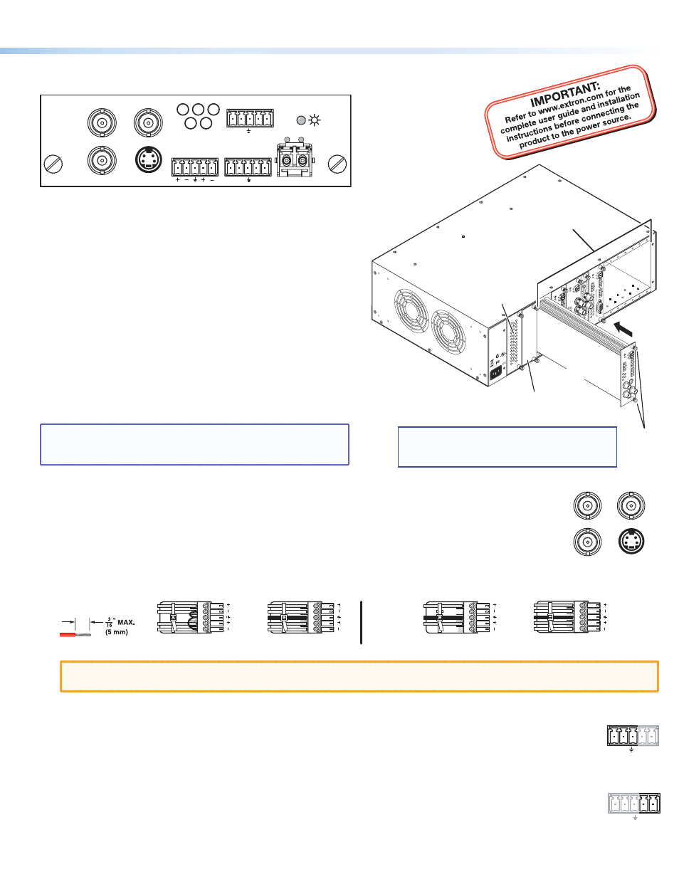
Step 1 — Install the Boards in the Enclosure
Install the Tx, Rx, or both boards in the PowerCage 1600 enclosure
slots as required. Use a screwdriver or other tool to tighten the two
screws that hold each board in place. (See the illustration at right.)
NOTE:
Ensure that the boards are flush with the rear of the
enclosure and that the screws are tightened securely
before applying power.
Step 2 — Connect the Input and Outputs
a.
Connect a low-resolution (composite, S-video, or component) video source to one or more Video Input
connectors on the transmitter. Connect a video output device to one or more Video Output connectors on
the receiver. (The video input connectors on the transmitter are identical in appearance to the video output
connectors on the receiver; both are shown at right.)
b.
Connect a balanced or unbalanced, stereo or mono audio input source to the Audio captive screw connector
on the transmitter. Connect a balanced or unbalanced stereo or mono audio output device to the Audio captive screw connector
on the receiver. (See the illustrations below.)
Unbalanced Stereo Output
Balanced Stereo Output
L
R
Ring
Sleeve(s)
Tip
Tip
Ring
L
R
Sleeve(s)
L
R
L
R
Tip
Tip
NO GROUND HERE.
NO GROUND HERE.
Unbalanced Stereo Input
Balanced Stereo Input
Ring
Sleeve (s)
Tip
Sleeve
Tip
Sleeve
Tip
Tip
Ring
Do not tin the wires!
CAUTION:
For unbalanced audio, connect the sleeves to the ground contact. DO NOT connect the sleeves to the negative
(–) contacts.
Step 3 — Connect Cables for Serial Control of an Output Device (Optional)
If you want the PowerCage FOX Tx/Rx AV units to pass serial data or control signals, such as for serial control of a
projector, connect the controlling device to the transmitter and the other device to the first three poles of the RS-232
Over Fiber captive screw connectors on both units.
Step 4 — Connect an Alarm (Optional)
For remote monitoring of the status of the Rx optical link on either unit, connect a contact closure device to the two
Alarm poles of the Remote RS-232/Alarm 5-pole captive screw connector on the unit. When no signal light is detected,
the two poles of the connector are shorted together to activate an alert (such as sounding an alarm, turning on a room
light, or sending an e-mail).
1
2
R
E
M
O
TE
RS-232
RS-232
O
VER FIBER
T
x
R
x
Tx
ALARM
R
x
OUTPUT
R
G
B
Po
werC
age
FO
X RX RG
B
T
x
R
x
L
R
A
U
D
IO
MONO
A
UDIO OUTPU
T
1
2
SHARP
GAIN
Y/VID
C
INPU
T
Po
we
rCa
ge
MT
P R
AV
T
x
Rx
HD/SDI INPUT
HD/SDI OUTPUT
S
MODE
Po
we
rCa
ge
FO
X 3G HD-SDI
1
2
R
E
M
O
TE
RS-232
RS-232
O
VER FIBER
T
x
R
x
Tx
ALARM
R
x
OUTPUT
R
G
B
Po
werC
age
FO
X RX
RG
B
T
x
R
x
L
R
A
U
D
IO
5A MAX.
100-240V 50/60H
z
N15
778
C
US
LIS
TED
1T2
3
I.T.
E.
1
2
REMO
T
E
RS-232
RS-232
O
V
ER FIBE
R
T
x
R
x
T
x
ALARM
Rx
VIDE
O
1
2
3
4
Po
we
rCa
ge
FO
X Rx
AV
T
x
R
x
L
R
A
UDI
O
Align board
and slide
into slot.
Screws
(2 per
board)
16 Available Single Board
Slots (8 double board slots)
Power
Supply
Optional
Redundant Power
Supply Slot
NOTE: Power supplies can occupy only these
two power supply slots. (Each power
supply can be mounted in either slot.)
1 2
REMOTE
RS-232
Tx Rx
ALARM
1 2
REMOTE
RS-232
RS-232
OVER FIBER
Tx Rx
Tx
ALARM
Rx
VIDEO INPUT
PowerCage
FOX Tx
A
V
Tx Rx
L
R
AUDIO
Y/VID
R-Y
B-Y/C
S-VID
RS-232
OVER FIBER
Tx Rx
Y/VID
R-Y
B-Y/C
S-VID
1
PowerCage
™
FOX Tx/Rx AV • Setup Guide