Mount the electrical box in the raceway – Extron Electronics MLC 60 Series (MLC 62 RS EU and the MLC 62 RS MK) Setup Guide User Manual
Page 4
68-2166-51 Rev. A
03 12
Extron Headquarters
+1.800.633.9876 (Inside USA/Canada Only)
Extron USA - West
Extron USA - East
+1.714.491.1500 +1.919.863.1794
+1.714.491.1517 FAX
+1.919.863.1797 FAX
Extron Europe
+800.3987.6673
(Inside Europe Only)
+31.33.453.4040
+31.33.453.4050 FAX
Extron Asia
+800.7339.8766
(Inside Asia Only)
+65.6383.4400
+65.6383.4664 FAX
Extron Japan
+81.3.3511.7655
+81.3.3511.7656 FAX
Extron China
+4000.398766
Inside China Only
+86.21.3760.1568
+86.21.3760.1566 FAX
Extron Middle East
+971.4.2991800
+971.4.2991880 FAX
Extron Korea
+82.2.3444.1571
+82.2.3444.1575 FAX
Extron India
1800.3070.3777
Inside India Only
+91.80.3055.3777
+91.80.3055.3737 FAX
© 2012 Extron Electronics
8.
Test the system to ensure that the MLC is functioning
properly.
9.
Mount the MLC.
Before mounting the MLC to a wall or furniture, make
sure that all device cables are connected to the MLC rear
panel. Disconnect power at the source from all devices in
the system.
a.
Align the MLC wall frame to the metal mounting
bracket, which you attached to the mounting surface
in step 3.
b.
Holding the wall frame in place on the bracket, press
the MLC into the frame until the two tabs on either
side of the unit snap into the opening of the metal
bracket, holding the MLC in place.
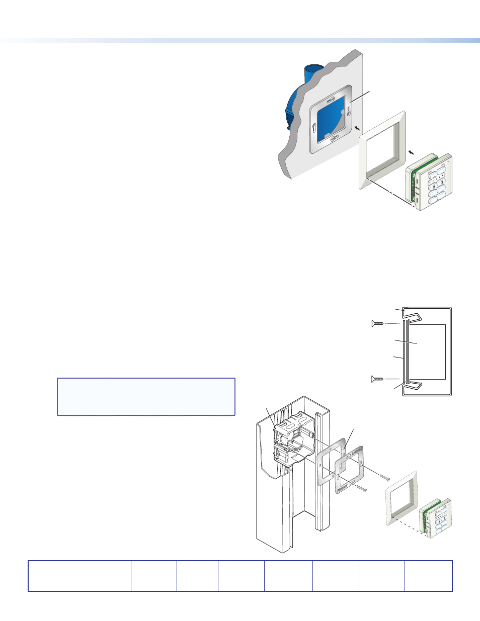
Mounting the MLC 62 EU in a Raceway
Using a Spacer (Optional)
If you are experiencing difficulty with the MLC staying in place when installed in a cable raceway, this may be due to a gap
between the metal mounting bracket and the wall frame.
When this gap exists, the tabs on the sides of the MLC do not reach the metal mounting bracket and the MLC does not snap
completely into the metal bracket.
You can remedy this situation by installing a spacer (provided with the MLC) between the metal mounting bracket and the
rim of the junction box. This spacer appears very similar to the metal mounting bracket, except that it has holes instead of
slots for the mounting screws, is engraved with the words “Optional Spacer” and “Place behind bracket,” and has a slightly
larger center opening than the metal mounting bracket.
1.
Mount the electrical box in the raceway.
2.
Attach the spacer to the electrical box by inserting two of the included screws in the
holes at the sides of the spacer. Leave the screw heads protruding approximately
1/8 inch from the surface of the spacer.
3.
With the “Front” label facing toward you, place the metal mounting bracket onto the
spacer so that the screw heads pass through two of the slotted holes in opposite sides
of the bracket.
NOTE: Ensure that the surface of the mounting
bracket containing the word “Front” is
facing out (away from the spacer and
junction box).
4.
Rotate the mounting bracket as necessary to ensure that
the MLC will be positioned straight on the mounting
surface and not skewed to either side.
5.
Tighten the screws to secure the bracket to the spacer.
6.
Pull the cables through the electrical box and the wall
frame.
7.
Disconnect power from all devices at the source and
connect all cables to the MLC.
8.
Align the wall frame with the metal mounting bracket
on the mounting surface.
9.
Press the MLC into the wall frame until the unit snaps
into place.
4
Electrical
Junction Box
Wall Frame
Metal Bracket
MLC 62 RS EU
VOLUME
DISPLA
Y
MUTE
LAPTOP
OFF
ON
PC
VIDEO
Cable Raceway
Junction Box
Wall Frame
Metal Bracket
MLC 62 RS EU
VOLUME
DISPLA
Y
MUTE
LAPTOP
OF
F
ON
PC
VIDE
O
Metal Spacer
Junction Box
Mounting Bracket
Spacer
Raceway