Front panel features – Extron Electronics MVC 121 Plus User Guide User Manual
Page 14
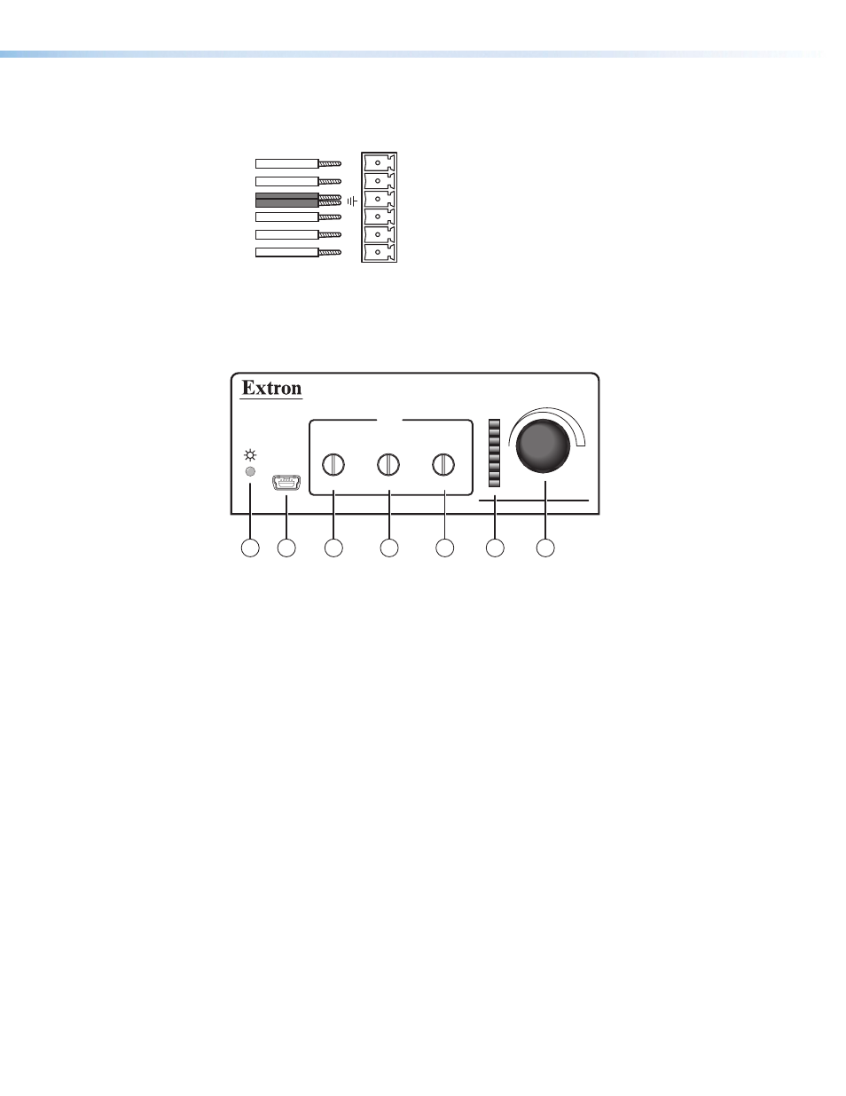
Both the RS-232 and the digital input connectors may be used simultaneously by using
a 6-pin captive screw connector with two wires sharing the same ground connector
(see the diagram below).
RS-232
DIGI IN
Tx Rx 1 2 3
i
Reset — The recessed reset button is used to access various modes of resets. The
green power LED on the front panel indicates what mode of reset was accessed (see
the
MVC 121 Plus Hardware Reset Modes
section for additional details).
Front Panel Features
VOLUME
CONFIG
MIX
MIC
MIC
LINE
3
2
1
MIXER/VOLUME CONTROLLER
MVC 121 Plus
2
1
3
4
5
6
7
Figure 4.
MVC 121 Plus Front Panel
a
Power/Reset LED — Green power indicator lights when the MVC 121 Plus is
operational. The LED also blinks per mode reset (see the
section).
b
Configuration (Config) port — Connect a PC to the USB mini B-type connector for
configuring the MVC using the DSP Configurator software. The MVC 121 Plus USB
driver must be installed prior to using the port.
c
Mic 1 gain control — Rotating the encoder screw clockwise increases the gain
setting, rotating the encoder screw counterclockwise decreases the gain. This
adjustment controls the single gain point in the mix matrix that mixes mono mic 1
levels to the stereo output bus.
The gain adjustment is indicated by the LED indicator bar (f). When the encoder
screw rotation has stopped for three seconds or longer, the LED indicator returns to
the output meter indication.
d
Mic 2 gain control — Rotating the encoder screw clockwise increases the gain
setting, rotating the encoder screw counterclockwise decreases the gain setting. This
adjustment controls the single gain point in the mix matrix that mixes mono mic 2
levels to the stereo output bus.
The gain adjustment is indicated by the LED indicator bar (f). When the encoder
screw rotation has stopped for three seconds or longer, the LED indicator returns to
the output meter indication.
MVC 121 Plus • Installation
8