S-video, Msw 4sv rs only) inputs to video sour, Msw 4sv rs only) outputs to video displays – Extron Electronics MSW 4V rs User Guide User Manual
Page 11: Connect the rs-232 captive screw connector, Connect the contact captive screw connector
b
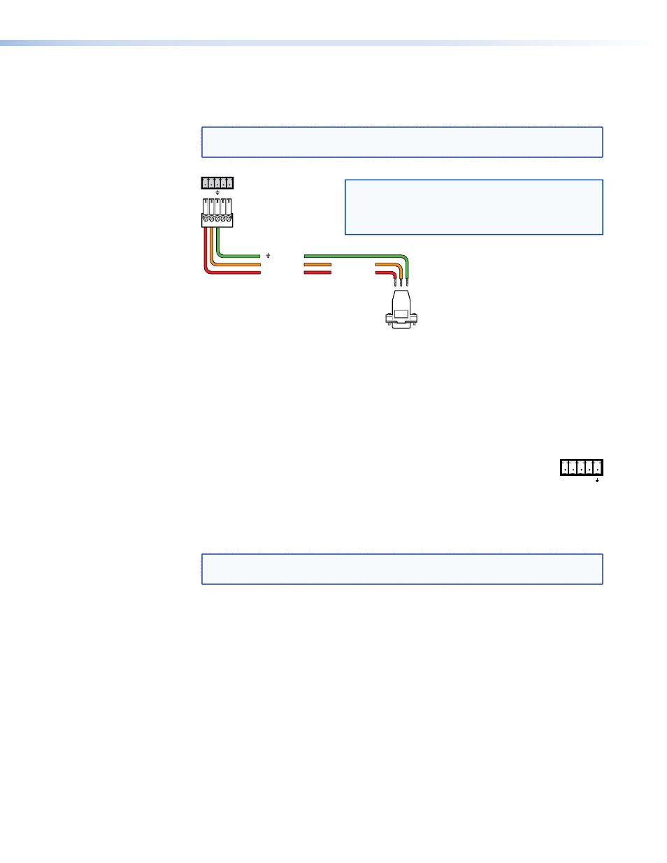
RS-232 connector — Connect a cable with a 3.5 mm, 5-pole captive screw connector
to this port for bidirectional RS-232 communication. Wire the connectors as shown
below.
NOTE: The Tx pin on the switcher connects to the Rx connector on the PC; the Rx
pin on the switcher connects to the Tx connector on the PC.
To Computer
Rear Panel RS-232 Port
Tx Rx
9-pin HD
Connector
Ground
Transmit
Rx Receive
Tx
Green
Orange
Red
Transmit (Tx)
Receive (Rx)
3
2
Connect a ground wire between the switcher
and the computer or control system. If you
use cable that has a drain wire, tie the drain
wire to ground at both ends.
NOTE:
Figure 4.
RS-232 Connector Wiring
This port has the following RS-232 protocol:
• 9600 baud
• 1 stop bit
• No parity
• 8 data bits
See “
Command and Response Table for SIS Commands
” on page 19
for the SIS commands used to communicate with the MSW switcher with
RS-232.
c
Contact connector — Connect a remote contact closure device to the MSW for
remote control of the switcher. You can also daisy chain the unit to other MSWs using
this 5-pole captive screw connector. This allows remote control of the other switchers.
NOTE: The switcher must be in normal (manual) mode for contact closure to
To select an input using a contact closure device, such as an Extron CCR 204 Contact
Closure Remote Control or a locally constructed device, momentarily short the pin
for the desired input number to logic ground (pin 5). To force one of the inputs to be
always selected, leave the short in place. The short overrides any front panel input
selections.
You can also daisy chain multiple MSWs by using the contact connector. This allows
for front panel control of all switchers (for example, touch the input button on one
MSW to switch all MSWs). Wire pin 1 to pin 1, pin 2 to pin 2, and so on.
d
S-video output (MSW 4SV rs only) — Connect an S-video display or other device to
this 4-pin mini DIN connector for the S-video output.
e
S-video inputs 1 through 4 (MSW 4SV rs only) — For each input, connect an
S-video source to one of these 4-pin mini DIN connectors.
CONTACT
1 2 3 4
MSW 4V rs and MSW 4SV rs • Panel Features
5