Front panel features, Ol (see – Extron Electronics MTP 15HD RS Series User Guide Rev. A User Manual
Page 10
Front Panel Features
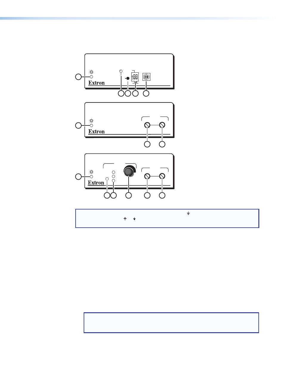
See figure 2 below to identify the front panel features on the transmitter and receiver.
MTP RL 15HD RS Receiver
RGB
PEAKING
LEVEL
M T P S E R I E S
MTP RL 15HD RS SEQ Receiver
RGB
DELAY
PEAKING
LEVEL
RED
GREEN
BLUE
SELECT
M T P S E R I E S
6
7
1
6
10
9
8
7
1
MTP T 15HD RS Transmitter
M T P S E R I E S
50 Hz
RECORD
60 Hz
SPARE
EDID
SELECT
ON
1
4
5
3
2
Figure 2.
MTP Front Panels
NOTE: Control signal ground pins may be labeled as or “G”. Audio ground pins may
be labeled as or .
The wiring and function are the same, whichever way your product is labeled.
a
Power LED — The LED indicator lights when the unit is receiving power.
b
Record LED — The LED indicator flashes red during the EDID recording process to
indicate a new EDID being written to memory. The LED returns to a solid green after the
write completes.
c
Record button — The recessed record button is used to initiate recording of the EDID
of a display device (connected to the loop-out) to user-programmable memory position
0 on the rotary switch (
e
).
d
Vertical frequency DIP switch — The first DIP switch selects the vertical frequency for
the pre-programmed EDID. When switched to OFF (default position), the EDID selected
by the rotary positions 1 through E are based on 60 Hz. When switched to ON, they are
based on 50 Hz. The second DIP switch, marked SPARE, is not used.
NOTE: When the EDID select rotary switch (
e
) is in position 0 or F, the setting of
the first DIP switch is not applicable because the user-recorded or attached
display EDID is being used.
MTP 15HD RS Series • Installation and Operation
6