Microphone input – Extron Electronics MPS 112_112CS User Guide User Manual
Page 15
2-7
MPS Series • Installation
Connecting the 3.5 mm mini-plugs
1
.
Use pre-made Extron 3.5 mm audio cables,
or
cut bulk audio cable and solder the 3.5 mm mini-plug to the cable.
Sleeve ( )
Ring (R)
Tip (L)
3.5 mm Stereo Plug Connector
(unbalanced)
Figure 2-6 — 3.5 mm, mini-plug audio connector
2
.
Plug the 3.5 mm mini-plug connectors into the MPS 112.
Microphone input
Connecting the 1/4" (6.3 mm) microphone connector (MPS 112)
1
.
Use a pre-made 1/4" microphone cable,
or
cut bulk microphone cable and solder the 1/4" microphone connector to
the cable.
Tip (+)
Sleeve ( )
Figure 2-7 — 1/4" microphone connector
2
.
Plug the 1/4" microphone connector into the MPS 112.
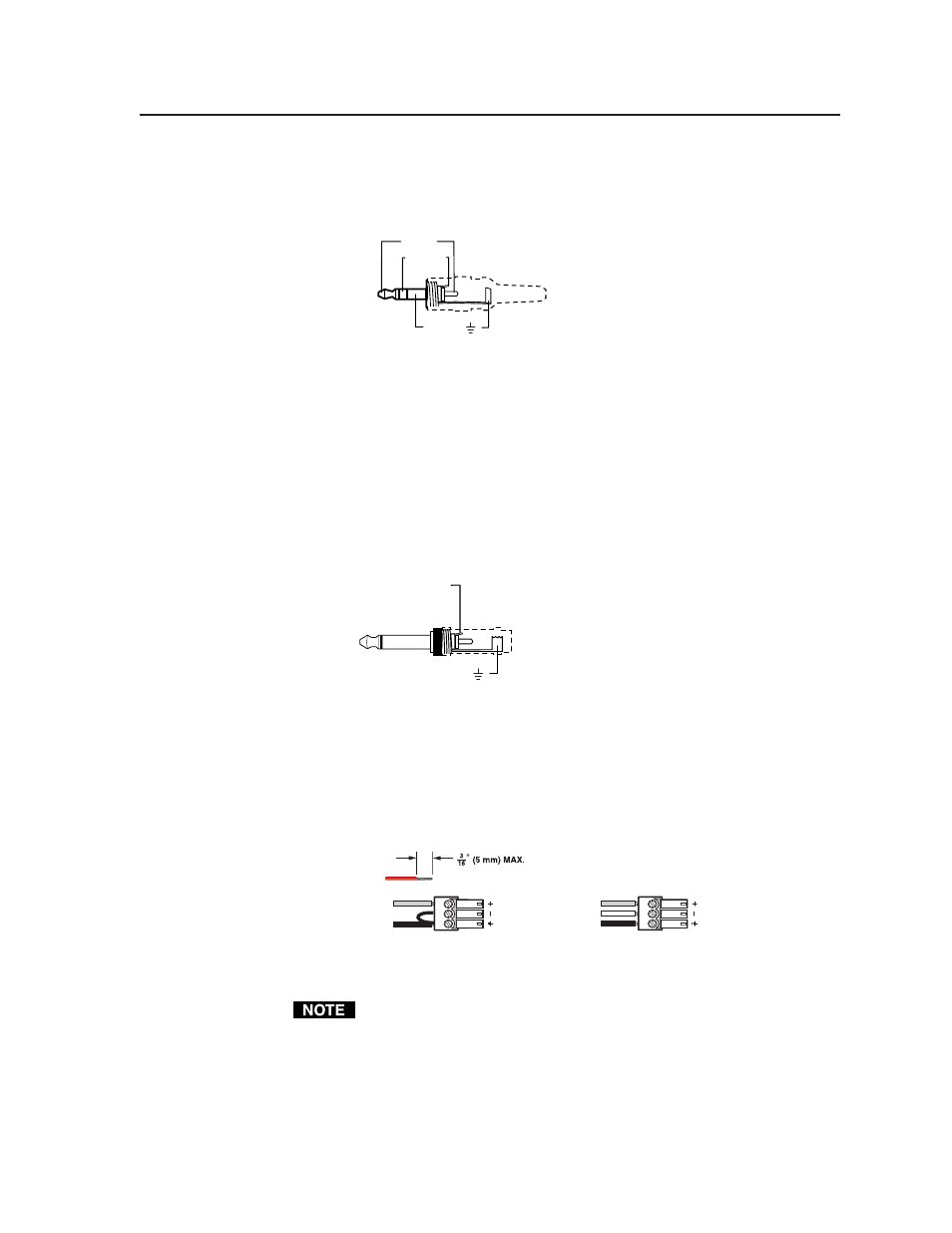
Connecting the 3-pole captive screw microphone connector (MPS 112CS)
1
.
Use a pre-made 3-pole captive screw microphone cable,
or
cut bulk microphone cable, and attach the 3-pole captive screw connector
to the cable.
Balanced Mic Input
Unbalanced Mic Input
Tip
Ring
Sleeve
Tip
Sleeve
Figure 2-8— 3.5 mm, 3-pole captive screw microphone connector
Do not tin the mic leads before installing into the connector. Tinned wires are
not as secure in the connector and could be pulled out.
2
.
Plug the 3-pole captive screw connector into the MPS 112CS.