Mps 601 • setup guide (continued), Connect control devices – Extron Electronics MPS 601 Setup Guide User Manual
Page 2
2
MPS 601 • Setup Guide (Continued)
Connect Control Devices
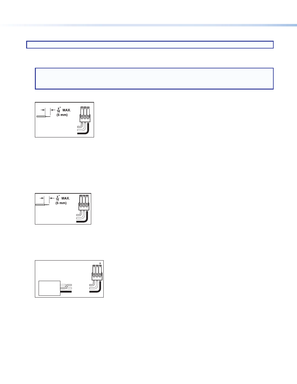
NOTE: Do not tin the leads. Tinned wires are not as secure in the connector and could be pulled out.
1.
Contact In/Tally Out —When a connected contact is grounded, the corresponding input is selected (see figure 1,
f
). At the
same time, the tally output closes causing the Show Me cable LED indicator to light.
NOTE:
•
For “Show Me” cables, the ground pin is optional.
•
Do not connect “Show Me” cables to the +V pin of the +V Port (see below).
The six contacts are mutually exclusive so that only one input can be selected at at time.
Ground (G)
Tally (NO)
Contact (NO)
T
C G
Do not tin
the wires!
Figure 2.
Contact In and Tally Out Connector Wiring
•
Contact (C) – Momentary closure of this pin to ground selects the corresponding number input. Selection is triggered at
the closure (grounding) of the pin, not the opening.
•
Ground (G) – Ground pin.
•
Tally output (C) – Controls the LEDs on the contact closure push button. When an input is selected, the tally LED for that
input is active.
3.
+V Port — All three pins constantly output +5 VDC, 200 mA total (shared between pins). The +V pins can provide power to
illuminate external tally LEDs (see figure 1,
g
).
+V
+V
+V
Do not tin
the wires!
Figure 3.
+V Connector Wiring
4.
Remote RS-232 — Serial port for connection of a host computer or controller using Simple Instruction Set (SIS™) or
Windows-based control software commands (see figure 1,
h
). The default protocol is 9600 baud, 8 data bits, 1 stop bit, and
no parity.
An IP Link
®
driver allows Extron IPL and MediaLink
®
devices to control the MPS 601 from the RS-232 remote connector.
Ground (
_
)
Receive (Rx)
Transmit (Tx)
Bidirectional
RS-232
Device
Ground (
_
)
Receive (Rx)
Transmit (Tx)
Rx
Tx
Do not tin
the wires!
Figure 4.
RS-232 Connector Wiring