Jmp 9600 • setup guide – Extron Electronics JMP 9600 Setup Guide User Manual
Page 2
2
f
LTC Input and Output connectors —
LTC Input connector — Connect an external LTC sync signal to this RCA connector for the media player to function as a sync slave
of another device.
LTC Output connector — Connect any downstream equipment that requires an LTC sync signal to this RCA connector to either
route the external sync signal throughout the system or for the media player to function as a sync master.
g
LAN ports — If desired, for IP control of the media player and content transfer, connect the player to a PC (using a crossover
cable) or to an Ethernet LAN (using a patch cable), via either of these RJ-45 connectors. You can use a PC to control the
networked player via MSVPP commands (serial ASCII commands for remote control of former Electrosonic
®
products), the Extron
Windows-based control program, or built-in HTML pages.
NOTES
: • Extron recommends that each LAN port have a unique IP address.
• The factory default IP and netmask (subnet mask) addresses are as follows:
LAN 1:
LAN 2:
Both ports:
IP address: 192.168.254.254
IP address: 192.168.254.253
Gateway address: 0.0.0.0
Netmask address: 255.255.0.0
Netmask address: 255.255.0.0
DHCP: Off
• Two LAN ports allow the media player to reside on two different subnets simultaneously.
h
Remote (RS-232) port 1 — Connect a host device, such as a computer or touch panel control to the player via this male 9-pin D
connector for serial RS-232 control or pass-through.
NOTES
: • Former Electrosonic products use a male connector, unlike most Extron products. You may need an adapter.
• Remote 1 can be set to Control (control the player), Passthrough (pass the signals to a controlled device), or Disabled.
• The media player can:
z
Operate at 300, 600, 1200, 4800, 9600, 19200, 38400, 57600, or 115200 baud rates
z
Use 7 or 8 data bits
z
Use no parity, even parity, or odd parity.
z
Use 1 or 2 stop bits
• Serial port Remote 2 is for factory use only. Do not attempt to control the player via the Remote 2 port.
NOTE:
The relay interface ports (items
i
,
j
, and
k
) provide optically-isolated digital inputs and relay outputs that can be
controlled by show control software. See the JMP 9600 Media Player User Guide for more details.
i
Digital Inputs 1 through 4 —
When enabled, these inputs allow the media player to sense a discrete signal, such as a
1
2
+ -
+ -
change in a switch position when it reads the inputs. Connect the desired discrete input line to the unit via two poles
(+ and –) of a 4-pole captive screw connector. See the drawing underneath item
j
and see the JMP 9600 Media Player
User Guide, for detailed wiring recommendations.
NOTE
: By factory default, automatic reports from Digital Inputs 1 through 4 are disabled, although they can be manually
read on command. To be made automatic, reports must be enabled using the Set input trigger on MSVPP
command. See the JMP 9600 Media Player User Guide, for MSVPP commands.
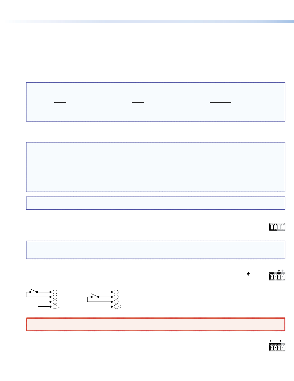
j
Power — This port provides +12 VDC power at up to 1.8 A, typically for use with Digital Inputs 1 through 4 (item
i
)
12V
POWER
above. The power is internally protected. Connect the device requiring power to two poles (12V and ground [ ]) of a
4-pole captive screw connector. See the drawing below and see the JMP 9600 Media Player User Guide, for detailed
wiring recommendations.
Correct
12V
Digital Input 1+
Digital Input 1–
Incorrect
Digital Input 1+
Digital Input 1–
12V
10
10
9
9
10
10
9
9
WARNING
: 12 VDC is always present on the Power port when the media player is powered on. Ensure that no conductive
material comes into contact with these terminals.
k
Relay Outputs — These ports are four sets of NO and NC relay contacts. Connect an external device that you want
NC C NO
NC
R1
to control to the player via three poles (normally closed [NC], common [C], and normally open [NO]) of the 4-pole
captive screw connectors.
JMP 9600 • Setup Guide