Front panel features and operation, Extron company contact information, Ircm-dv+ • setup guide (continued) – Extron Electronics IRCM-DV+ User Manual
Page 2: Step 5, Step 6, Step 7, Step 8
2
© 2011 Extron Electronics All rights reserved.
IRCM-DV+ • Setup Guide (Continued)
Step 5
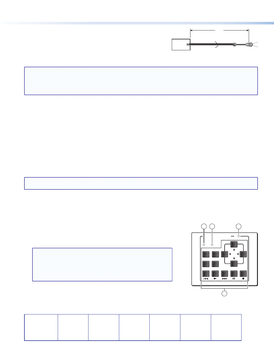
Connect IR Emitters (one per each VCR, DVD player, or other device
being controlled) to the MLC or System 5 IP, and affix each emitter head
near the IR receiver of the device (VCR, DVD player).
Step 6
Restore power to the devices and set up the MLC or System 5 IP.
NOTES:
•
The configuration should be created and uploaded to the MLC before the MLC is installed into the wall or
furniture.
•
Configuration and IR command learning require an RS‑232 or IP/LAN connection to the System 5 IP or the
MLC 104/226. See the user or setup guide for the MLC or switcher and the software help file for details on
installing, operating, and setting up that device.
a.
Associate the IRCM-DV+ with inputs on the MLC or System 5 IP. In Global Configurator, assign the DVD half of
the IRCM‑DV+ to an input button, then assign the VCR half to another input button. For detailed procedures, see
the Global Configurator Help file.
b.
For the System 5 IP or MLC 104 Plus or MLC 226 IP Series, if an Extron‑created driver is available for the VCR and the
DVD or the combination VCR‑DVD player, download the device driver(s) to the PC and load the commands to
the Global Configurator project.
c.
If needed, perform IR learning (the process by which the MLC or system switcher stores commands from an infrared
remote control) for each IRCM button for each device (VCR and DVD). See the the MLC or System 5 IP User Guide.
Step 7
Test the system.
•
Verify that the DIP switches on the IRCM are set correctly.
•
Verify that cables to and from the IRCM are wired the same at each end (pin A to pin A, pin B to pin B, and so forth).
•
Verify LED function and check the responses of the VCR and DVD players.
NOTE: You must recycle power to an MLC in order for it to recognize an IRCM‑DV+ or any other control modules that
have been added after initial power‑on.
Step 8
Once configuration and testing are complete, mount the MLC and the control module(s) into the wall/furniture.
Front Panel Features and Operation
a
DVD LED (amber) — Lights while the MLC or switcher input associated with
the DVD player is selected.
b
VCR LED (amber) — Lights while the input associated with the VCR is
selected.
NOTES:
•
When an input that is not associated with that part of the
IRCM‑DV+ is selected, LEDs
a
and
b
turn off.
•
The MLC or System 5 IP input must be selected (active) before
either part (DVD or VCR) of the IRCM‑DV+ can be activated and
control the DVD or VCR.
c
Tx (transmit) LED — This LED lights whenever an IRCM‑DV+ button is
pressed.
d
Function buttons — These buttons replicate whichever VCR and DVD player
controls you assigned to them during configuration.
Ground (−)
IR Signal (+)
IR Port on
MLC or
System 5 IP
100'
(30.5 m)
Figure 3.
IR Emitter Wiring
DVD & VCR CONTROL
PLAY NEXT/FWD PAUSE
STOP
TUNER
Tx
PREV/REW
ENTER
TITLE
MENU
TV/VCR
DVD
VCR
1
2
3
4
Figure 4.
Front Panel
68-689-50
Rev. A
08 11