Ewb 710 • installation guide (continued), Mounting the ewb 710, Mounting the tlp 710mv – Extron Electronics EWB 710 User Manual
Page 2
EWB 710 • Installation Guide (Continued)
Extron USA - West
Headquarters
+800.633.9876
Inside USA and
Canada Only
+1.714.491.1500
+1.714.491.1517 FAX
Extron USA - East
+800.633.9876
Inside USA and
Canada Only
+1.919.863.1794
+1.919.863.1797 FAX
Extron Europe
+800.3987.6673
Inside Europe Only
+31.33.453.4040
+31.33.453.4050 FAX
Extron Asia
+800.7339.8766
Inside Asia Only
+65.6383.4400
+65.6383.4664 FAX
Extron Japan
+81.3.3511.7655
+81.3.3511.7656 FAX
Extron China
+400.883.1568
Inside China Only
+86.21.3760.1568
+86.21.3760.1566 FAX
Extron Middle East
+971.4.2991800
+971.4.2991880 FAX
© 2011 Extron Electronics All rights reserved.
Mounting the EWB 710
1.
Decide where to mount the EWB 710. If
mounting to standard wood wall studs, locate the
center of the studs.
2.
Place the EWB 710 against the wall at the
mounting location. Use a level to ensure the box
is horizontal and mark the position of the four
holes.
3.
If required, drill four holes into the wall.
4.
Insert four screws (see the table on the previous
page) and attach the EWB 710 to the wall.
5.
Remove the required knockout and run conduit
or raceway to the EWB 710.
6.
Run cables through the conduit and the EWB 710 knockout.
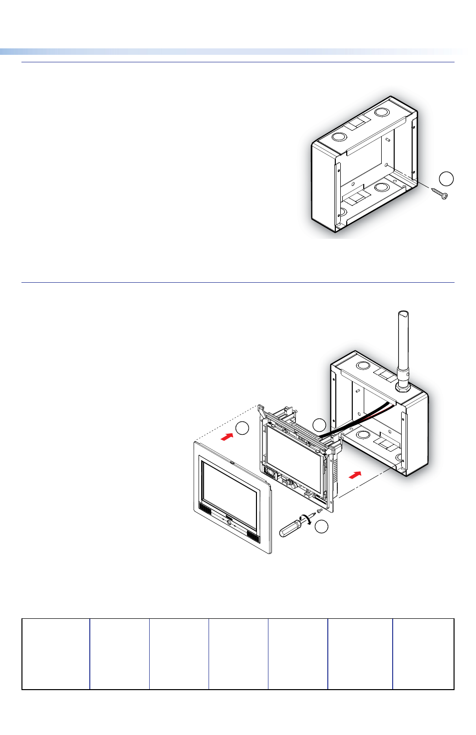
Mounting the TLP 710MV
1.
Remove the faceplate from
the Touchpanel.
2.
Attach the cables to the
back of the TLP 710MV
(see the TLP 710MV and
TLP 710TV User Guide).
3.
Secure the TLP 710MV to
the EWB 710 using the four
6-32 screws provided.
4.
Configure the Touchpanel
as described in the
TLP 710MV and TLP 710TV
User Guide.
5.
Snap the faceplate into
position (four clips on each
side).
68-2151-01
Rev. A 09 11
Mounting
Screws (4)
4
Extron
EWB 710
Wall Box
Extron
TLP 710MV
Extron
TLP 710MV
Faceplate
Extron
2
5
3