Extron Electronics XTRA Series User Manual
Page 19
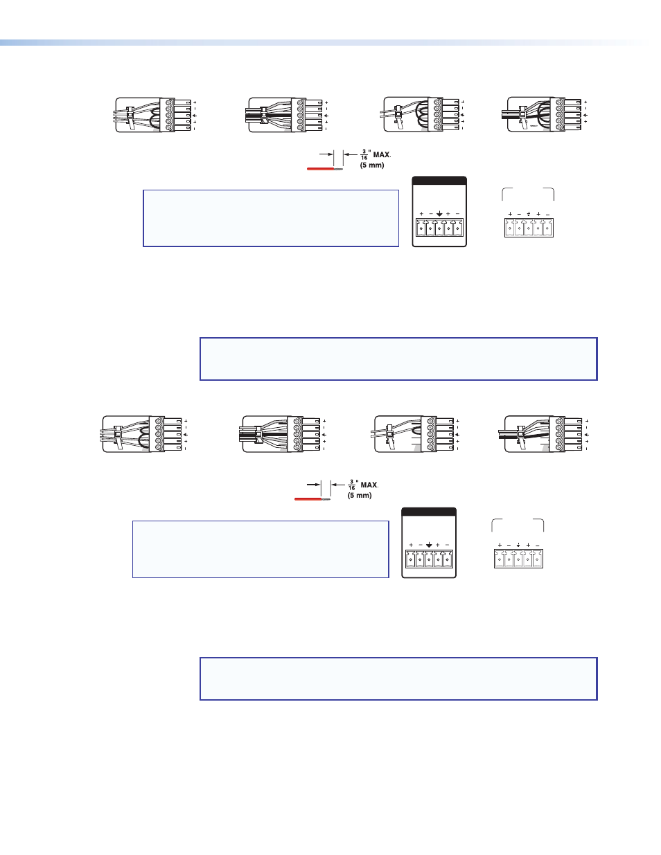
Do not tin the wires!
Balanced Stereo Input
Tip
Ring
Tip
Ring
Sleeves
LR
Unbalanced Stereo Input
Tip
Sleeve
Sleeve
Tip
LR
Unbalanced Mono Input
Tip
Sleeve
LR
Balanced Mono Input
Tip
Ring
Sleeve
LR
or
1
2
INPUTS
NOTE: The input connector receptacle may be
labeled one of two ways. The wiring and
function are the same, whichever way your
product is labeled.
INPUTS
1
2
â
Balanced or unbalanced stereo or mono audio input connector (XPA 2001) —
Wire the 3.5 mm 5-pin captive screw connector for balanced or unbalanced input.
NOTE: For mono input on the XPA 2001, because the left and right channels
are summed, only wire the left channel. No jumpering to the right channel is
needed.
Do not tin the wires!
Unbalanced Mono Input
Tip
Sleeve
LR
Balanced Mono Input
Tip
Ring
Sleeve
LR
Balanced Stereo Input
Tip
Ring
Tip
Ring
Sleeves
LR
Unbalanced Stereo Input
Tip
Sleeve
Sleeve
Tip
LR
NOTE: The input connector receptacle may be
labeled one of two ways. The wiring and
function are the same, whichever way your
product is labeled.
or
1
2
INPUTS
INPUTS
1
2
f
Remote control connector — The 3.5 mm 5-pin captive screw port is used to
remotely control two functions through contact closure (see the circuit diagram on the
following page).
NOTE: The remote control port may be labeled one of two ways (see the image
on the following page). The wiring and function are the same, whichever way
your product is labeled.
Pins V, C, and G (1, 2, and 3) control volume by varying the DC voltage from 0 V
(full attenuation) to 10 V (maximum volume) with full muting in effect when pin C is
connected to ground (pin G). Use the included 3-pin captive screw connector (see
XTRA Series Half-Rack Audio Power Amplifiers • Operation
13