Application diagrams, Application with “show me” cables, Ctr 8 • panels and cabling 4 – Extron Electronics CTR 8 User Guide User Manual
Page 9: Extron ctr 8, Transmit (tx) ground (g), Ctr 8 switcher, Extron in1606, Extron ipl 250
CTR 8 • Panels and Cabling
4
c
Remote RS-232 port — Connect the serial port of a control computer to this female
captive screw connector as shown below.
CG
T+
V
Contact (C)
Ground (G)
Tally output (T)
Tally voltage (+V)
Transmit (Tx)
Receive (Rx)
Ground (G)
Tx
Rx
RS-232
G
Transmit (Tx)
Ground (G)
Tx
COM
G
Figure 5.
RS-232 Input Wiring
The protocol for the RS-232 port is 9600 baud, 8 data bits, 1 stop bit, no parity.
d
COM switcher port — Connect an Extron switcher to this female captive screw
connector as shown below. Only connect the Tx and G pins of the CTR 8.
Transmit (Tx)
Ground (G)
Tx
COM
G
Rx
Tx
REMOTE
CTR 8
Switcher
G
Figure 6.
COM Input Wiring
The protocol for the COM port is 9600 (default), 19200, 38400, or 57600 baud; 8 data
bits, 1 stop bit, no parity.
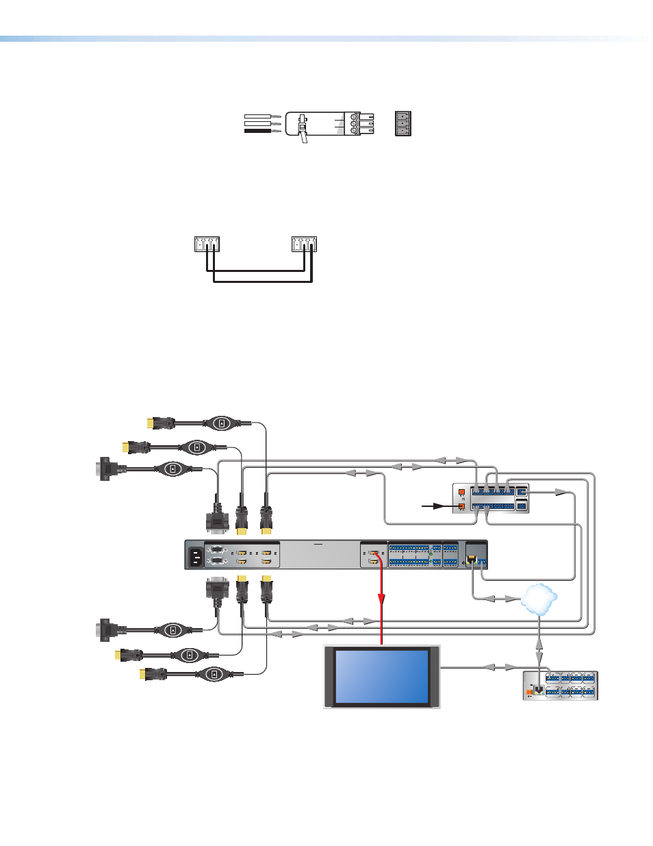
Application Diagrams
Application with “Show Me” Cables
12V
POWER IN
POWER OUT
RS-232
Tx
4
C G T +V
3
C G T +V
2
C G T +V
1
C G T +V
8
C G T +V
7
C G T +V
6
C G T +V
5
C G T +V
G
Tx Rx G
1.0A
MAX
1.0A
MAX
CONTACT IN / TALLY OUT
COM
REMOTE
100-240V ~ 50/60 Hz
-- A MAX
1
2
CONFIGURABLE
HDMI
IN1606
HDMI
5
6
HDMI
A
B
3
4
INPUTS
OUTPUTS
AUDIO INPUTS
OUTPUTS
REMOTE
L
1
R
L
2
R
L
3
R
L
4
R
L
5
R
+48V
+48V
1
2
L
R
VARIABLE
Tx Rx
RS-232
G
LAN
RESET
1
2
MIC/LINE
L
6
R
INPUT
LAN
POWER
12V
500mA
MAX
1 2 3 4
COM 3
IR
3
S G S G
Tx Rx
4
RELAY
3
4
COM1
Tx Rx
RTS CTS
COM 2
IR
1
S G S G
Tx Rx
2
RELAY
1
2
RS-232
RS-232
Ethernet
Ethernet
Flat Panel Display
HDMI Video and
Embedded Audio
Contact Closure and Tally
Contact Closure and Tally
Power
Supply
Extron
CTR 8
Eight Input Contact
Closure to RS-232
Control Module
Extron
IN1606
Scaling Presentation
Switcher
VGA/HDMI “Show Me” Cables
TCP/IP
Network
Extron
IPL 250
IP Link Control
Processor