Step 3 — attach modules to optional mounting frame, Step 4 — cable inputs, Step 5 — test the system – Extron Electronics DAV_DAS101CM Series Setup Guide User Manual
Page 2: Step 6 — set the sharpness and peaking, Step 7 — disconnect power, Step 8 — mount the modules, Step 9 — connect power
Setup Guide — DAV101CM, DAS101CM Series (cont’d)
68-757-50
Rev. A
01 10
NFPA 70, article 75 and the Canadian Electrical Code part 1, section 16. The power
supply shall not be permanently fixed to building structure or similar structure.
Step 3 — Attach modules to optional mounting frame
For wall, furniture or rack installations, attach the module(s) to a CPM Series mini architectural
adapter plate (MAAP) frame or to a rack-mountable frame.
Step 4 — Cable inputs
Attach cables from the source device(s) to the front panel input connector(s).
•
Cable a computer to the DAV’s 15-pin HD connector, which provides ID bit termination on
pins 4 and 11.
•
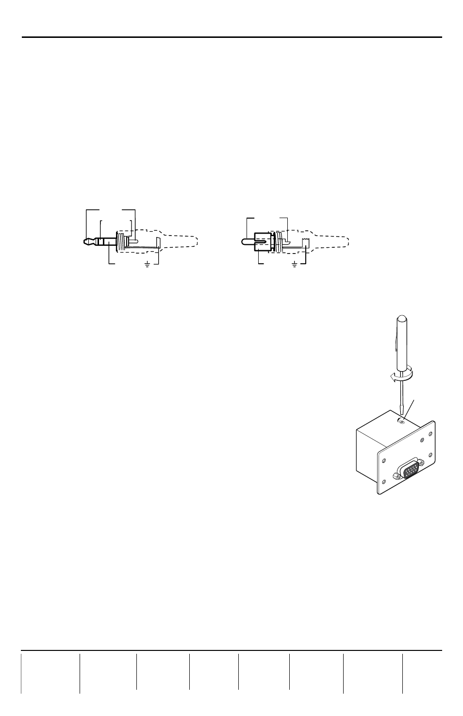
Connect an unbalanced, line level stereo audio source to the DAS. Audio connectors can be
wired as shown below.
Tip (+)
Sleeve ( )
Sleeve ( )
Ring (R)
Tip (L)
3.5 mm TRS Stereo Plug (unbalanced)
for DAS101CM-1, -2, -5
RCA Plug (unbalanced)
for DAS101CM-3, -4, -6
Step 5 — Test the system
Verify correct cabling and connector wiring and test the system:
a.
Power on all the devices and monitor the audio/video output. Each
DAV module’s Power LED is lit while the unit receives power.
b.
If needed, power off the devices, disconnect the modules’ power supply,
correct cabling or wiring errors, then restore power.
Step 6 — Set the sharpness and peaking
For a DAV101CM, set the peaking control using a small screwdriver,
as shown at right. While viewing the output image, rotate this
potentiometer to select the setting that gives the clearest pictures.
C
Using a large screwdriver can break the potentiometer.
Step 7 — Disconnect power
Disconnect power from the module(s) and other devices.
Step 8 — Mount the modules
•
For wall or furniture mounting, mount the modular connector frame and module(s) to the
wall or furniture.
•
For device mounting, mount the module(s) to the device’s faceplate.
•
For rack mounting, mount the rack-mountable frame to the equipment rack.
•
For all installations, place the connector plate onto or against the mounting surface and
secure it to wall, furniture, device, or rack with the provided screws or bolts. Be careful not
to damage the cables.
Step 9 — Connect power
Restore power to the devices. You have completed the installation.
DA
V1
01C
M
VGA LINE DRIVER
VID
EO
IN
PU
T
PO
WE
R
PE
AK
ING
Peaking