System 5 cr cr cr cr cr options – Extron Electronics Power Sensor System 5cr User Manual
Page 2
1
System 5
cr
Options • Power Sensor • User’s Guide • Extron
Installation and Operation
Extron • System 5
cr
Options • Power Sensor • User’s Guide
2
Installation and Operation
System 5
cr
cr
cr
cr
cr
Options
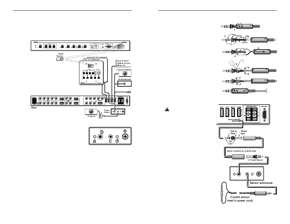
The Display Power Sensor is one of the options available for the
System 5 pictured near the bottom of Figure 1. When properly
installed, the sensor will “tell” the System 5cr when the projector is
turned ON. If the System 5 sends a Display Power On command,
for example, and the sensor does not detect the power coming on,
the System 5 can send the command again (up to three times).
Figure 1. System 5cr Options and Accessories
Power Sensor (60-271-01)
The sensing device is designed to
attach to the power cord of the
projector being used with the
System 5. Because different
projectors use different amounts of power, the Power Sensor must
be adjusted for the projector in each installation.
Use these illustrated procedures for making the cable and
connecting the sensor to the System 5, as well as for adjusting
the sensitivity. The components on the control panel shown above
have the following functions:
a. Power LED lights when receiving power from the System 5.
b. A 3.5 mm stereo mini jack, (tip/ring/sleeve) to System 5.
c. A 2.5 mm jack with two contacts for the current sensor.
d. A sensor LED that lights when the unit senses current (power).
e. A knob for adjusting the sensitivity level. See back page.
Velcro on the top of the enclosure allows it to be mounted in an
appropriate place. The power sensor must be installed close to
the projector.
Making Cables
Extron provides the 3.5 mm
connectors with the Power
Sensor, however a cable will
have to be made to fit the
installation requirements.
Use the information on this
page when making the cable
and connecting it. Figure 2
shows how to wire a 3.5 mm
connector for the Power
Sensor voltage, signal and
ground, as used between the
System 5 and the Power
Sensor unit. A finished cable
is shown at the bottom of
Figure 2. Connect both ends
of the cable the same, for a
one-to-one configuration.
Figure 2. Solder wires to tip, ring, and sleeve.
___ When finished, either
end of the cable can plug
to either device.
However, because there
will be +12 volts on the
tip (from the System 5) it
is best to plug the cable
to the Power Sensor first,
and then to the
System 5.
Figure 3 shows how the
cable connects between
the System 5 jack (rear
panel) and the Power
Sensor. The contact
assignments are:
Tip = +12 volts
Ring = Signal
Sleeve = Ground
See the next page for
connecting and
adjusting the current
sensor device.
Figure 3. Cables contact assignments
IR Emitter
8
3-5mm-cable-oct.eps
Unscrew cover.
Locate components.
Slide cover over
Strip wires and insert in holes.
Solder 3 wires.
Bend tabs over cable insu
Push connectors inward.
Screw cover onto connector.
○
○
○
○
○
○
○
○
○
○