New installation, Installation guide — bb 700m, cont'd – Extron Electronics BB 700M User Manual
Page 2
Extron
USA - West
Headquarters
+800.633.9876
Inside USA / Canada Only
+1.714.491.1500
+1.714.491.1517 FAX
Extron
USA - East
+800.633.9876
Inside USA / Canada Only
+1.919.863.1794
+1.919.863.1797 FAX
Extron
Europe
+800.3987.6673
Inside Europe Only
+31.33.453.4040
+31.33.453.4050 FAX
Extron
Asia
+800.7339.8766
Inside Asia Only
+65.6383.4400
+65.6383.4664 FAX
Extron
Japan
+81.3.3511.7655
+81.3.3511.7656 FAX
Extron
China
+400.883.1568
Inside China Only
+86.21.3760.1568
+86.21.3760.1566 FAX
Extron
Middle East
+971.4.2991800
+971.4.2991880 FAX
© 2010 Extron Electronics. All rights reserved.
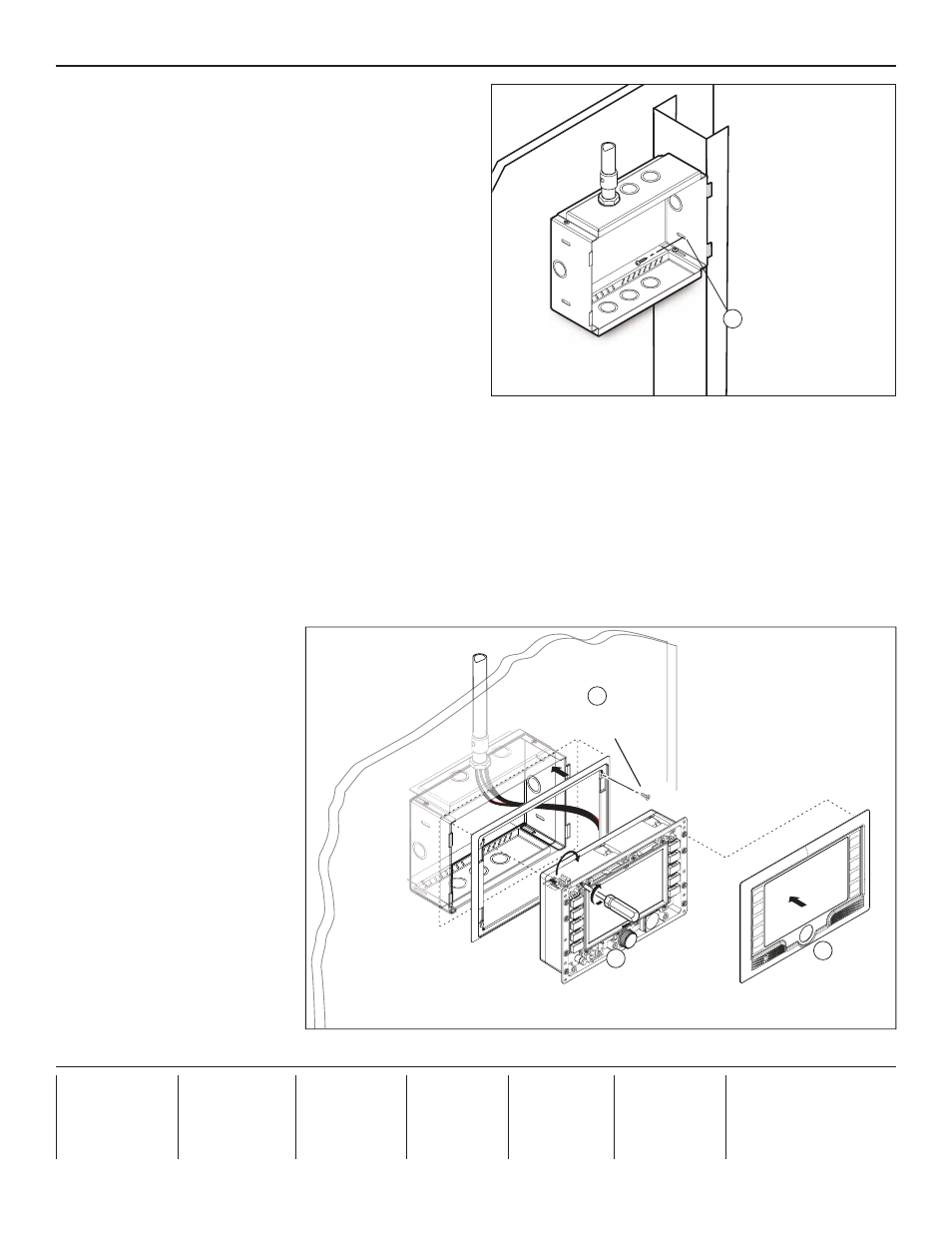
Installation Guide — BB 700M, cont'd
New Installation
1.
Before the drywall sheet has been secured to the studs,
place the BB 700M wall box in a suitable place so that the
tabs on the side of the box are flat against the stud.
2.
Secure the BB 700M to a vertical stud (metal or wooden)
using two nails or screws (see figure 4).
3.
Run the cable conduits to the box and connect them to one
of the available punch-outs. Leave enough cable at the end
to provide slack for installing the TouchLink panel.
4.
Measure the position of the wall box, and mark and cut a
hole in the drywall where the wall box is placed.
N
The hole is 9.55 inches (24.26 cm) wide x 6.55 inches
(16.64 cm) high.
5.
Secure the drywall to the studs.
N
The outer edge of the wall box is behind the drywall.
6.
If required, paint the drywall. Insert the cardboard cover
(provided) into the wall box to avoid getting paint on the BB 700M.
7.
Secure the TR 700M trim ring to the drywall, using four screws (see figure 5).
8.
Connect the cables to the back of the TLP 700MV (see the User's Manual, which is available from
). Feed
any excess cable back into the conduit.
9.
Configure the TLP
TLP 700MV.
10.
Fold the locking arms into their recesses on the side of the TLP 700MV and slide the unit into the wall box. Tighten the
screws on the front of the unit so that the locking arms rotate into place behind the top and bottom plates of the BB 700M and
hold the unit in place (see figure 5).
11.
Snap the faceplate into
position (see figure 5).
68-1895-01
Rev. A
03 10
Mounting Screws (2)
Extron BB 700M
Wall Box
for Wall-mounting
Extron TLP 700MV
2
Figure 4
Faceplate snaps to unit
(4 plcs ea side).
Tighten screws to
rotate locking arms.
Trim Ring
7
10
11
Screws (4)
Figure 5