Above base stud in-wall cabling, Extron contact information, Avtrac – Extron Electronics AVTrac Retrofit Transition Adapter User Manual
Page 2
2
AVTrac
®
Retrofit Transition Adapter • Setup Guide (Continued)
Extron USA - West
Headquarters
+800.633.9876
Inside USA/Canada Only
+1.714.491.1500
+1.714.491.1517 FAX
Extron USA - East
+800.633.9876
Inside USA/Canada Only
+1.919.863.1794
+1.919.863.1797 FAX
Extron Europe
+800.3987.6673
Inside Europe Only
+31.33.453.4040
+31.33.453.4050 FAX
Extron Asia
+800.7339.8766
Inside Asia Only
+65.6383.4400
+65.6383.4664 FAX
Extron Japan
+81.3.3511.7655
+81.3.3511.7656 FAX
Extron China
+400.883.1568
Inside China Only
+86.21.3760.1568
+86.21.3760.1566 FAX
Extron Middle East
+971.4.2991800
+971.4.2991880 FAX
10.
Terminate the ground wires with the provided ring terminals. Splice the wires from the AVTrac AC conduit to an AC
cord or conduit. Secure the ground wires to the stud on the inside of the adapter.
NOTE:
The AVTrac Retrofit Transition Adapter kit comes with a six foot (183 cm) AC power cord and a three foot
(91 cm) liquid‑tight flex conduit. All the accessories required for termination are provided for installation.
Check with your local electrical codes to determine which is required for your installation.
11.
Replace the cover using the screws removed in step 2 (see the figure below).
12.
Finish the AVTrac installation as described in the AVTrac User Guide.
Above Base Stud In-Wall Cabling
This application is one solution to bring the AVTrac system
into compliance with the building codes of cities where
cutting the base stud is prohibited. The cables are run
through the wall space. The height of the box and large
rear opening allow access to the wall cavity without cutting
the base stud.
1.
Prepare the site for AVTrac installation. Remove the
carpet from the floor and the baseboard from the wall.
For complete information, see the AVTrac User Guide,
available online at
www.extron.com.
2.
Remove the cover from the AVTrac Retrofit Transition
Adapter. Four screws (two on the top panel and two at
the bottom of the front panel) hold the cover in place.
3.
Remove the isolation panel as the high voltage is
separated in the conduit.
4.
Position the AVTrac base track, connectivity box,
retrofit adapter, and plastic ramps. Pre‑drill the
mounting holes in the track and ramps. Remember to
pre‑drill at least three holes for securing the adapter to
the floor next to the wall.
5.
Mark the position of the opening at the back of the adapter on the wall. Make sure the bottom of the hole is higher
than the top of the base wall stud.
6.
Remove the adapter and the base track.
7.
Cut a hole in the wall up to 3.5 inches (89 mm) wide and 2 inches (51 mm) high.
8.
Clean away any dust or debris after cutting the hole.
9.
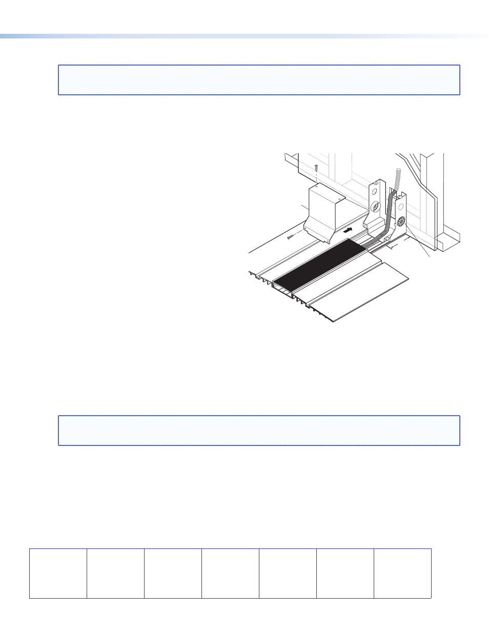
Install the AVTrac base track, connectivity box, and plastic ramps as described in the AVTrac User Guide.
NOTE:
The AVTrac cover track runs up to the front edge of the adapter; the base track runs all the way to the wall,
under the adapter. When measuring and cutting the cover track, it must be 3 inches (75 mm) shorter than
the base track (see the figure above).
10.
Secure the adapter through the base track to the floor using the masonry screws provided with the AVTrac.
11.
If necessary, secure the adapter to the wall using screws that are appropriate for the wall type.
12.
Route the AV cables and conduit from the AVTrac through the hole in the wall.
13.
Connect the AC conduit to the main power circuit at a UL‑approved junction box.
14.
Replace the cover using the screws removed in step 2.
15.
Finish the AVTrac installation as described in the AVTrac User Guide.
68‑1752‑50
Rev A
10 10
Cover
Extron AVTrac®
Floor Mount Raceway System
for A/V Connectivity
Extron
Retrofit
Transition
Adapter
Conduit
3"