Setup and operation, Rear panel features and cabling, Ab c d – Extron Electronics BUC 202 User Guide User Manual
Page 7: Ac power, Input connector, Trim adjustment, Output connector figure 2. buc 202 rear panel
Setup and Operation
The Setup and Operation section describes:
•
Rear Panel Features and Cabling
•
•
Rear Panel Features and Cabling
100-240V 50/60 Hz
0.2A MAX
1
2
1
2
TRIM
OUTPUTS
BUC 202
15
18
0
21
3 6
9
12
-15
-18
-21
-3
-6
-9
-12
15
18
0
21
3 6
9
12
-15
-18
-21
-3
-6
-9
-12
1
2
INPUTS
A
B
C
D
A
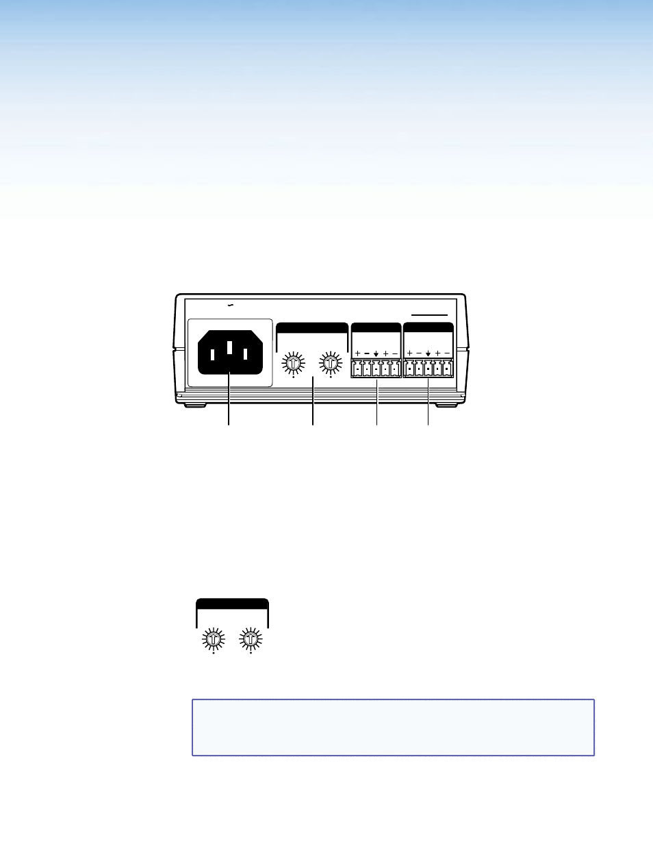
AC power
C
Input connector
B
Trim adjustment
D
Output connector
Figure 2.
BUC 202 Rear Panel
A
AC power — Connect to standard AC power: 100 to 240 VAC, at 50 or 60 Hz.
B
Trim adjustment (channels 1 and 2) — Adjust the audio input level for the channel
using the 16-position rotary switch. This switch sets the level in 3 dB increments from
-21 dB to +21 dB. The arrow on the shaft indicates the current setting.
1
2
TRIM
15
18
0
21
3 6
9
12
-15
-18
-21
-3
-6
-9
-12
15
18
0
21
3 6
9
12
-15
-18
-21
-3
-6
-9
-12
Figure 3.
BUC 202 16-position Rotary Switches
NOTE: Unity gain (0 dB) for both channels is at the 12 o’clock (vertical) position
with the arrow on the shaft pointing to the 0 position. When the switch is set to the
bottom position (indicated by a dot) the signal is muted (see
on page 5).
BUC 202 User Guide • Setup and Operation
3