Installation and operation, cont’d, Caution, Buc 102 • installation and operation – Extron Electronics BUC 102 User Manual
Page 12
BUC 102 • Installation and Operation
Installation and Operation, cont’d
8
The blue connector does not have the extended tail or the
included tie-wrap.
Do not tin the power supply leads before installing in the
direct insertion connector. Tinned wires are not as
secure in the connectors and could be pulled out.
After making any adjustments to the BUC 102, either
via the front panel controls, SIS commands, or the
Extron Audio Products Control Program, wait at least
10 seconds after making those changes before
disconnecting power to the BUC 102. Failure to
observe the 10-second timeout may result in those
adjustments not being saved.
Your BUC 102 may have shipped with a blue captive
screw connector. This blue connector can be plugged
into either a blue or an orange power receptacle.
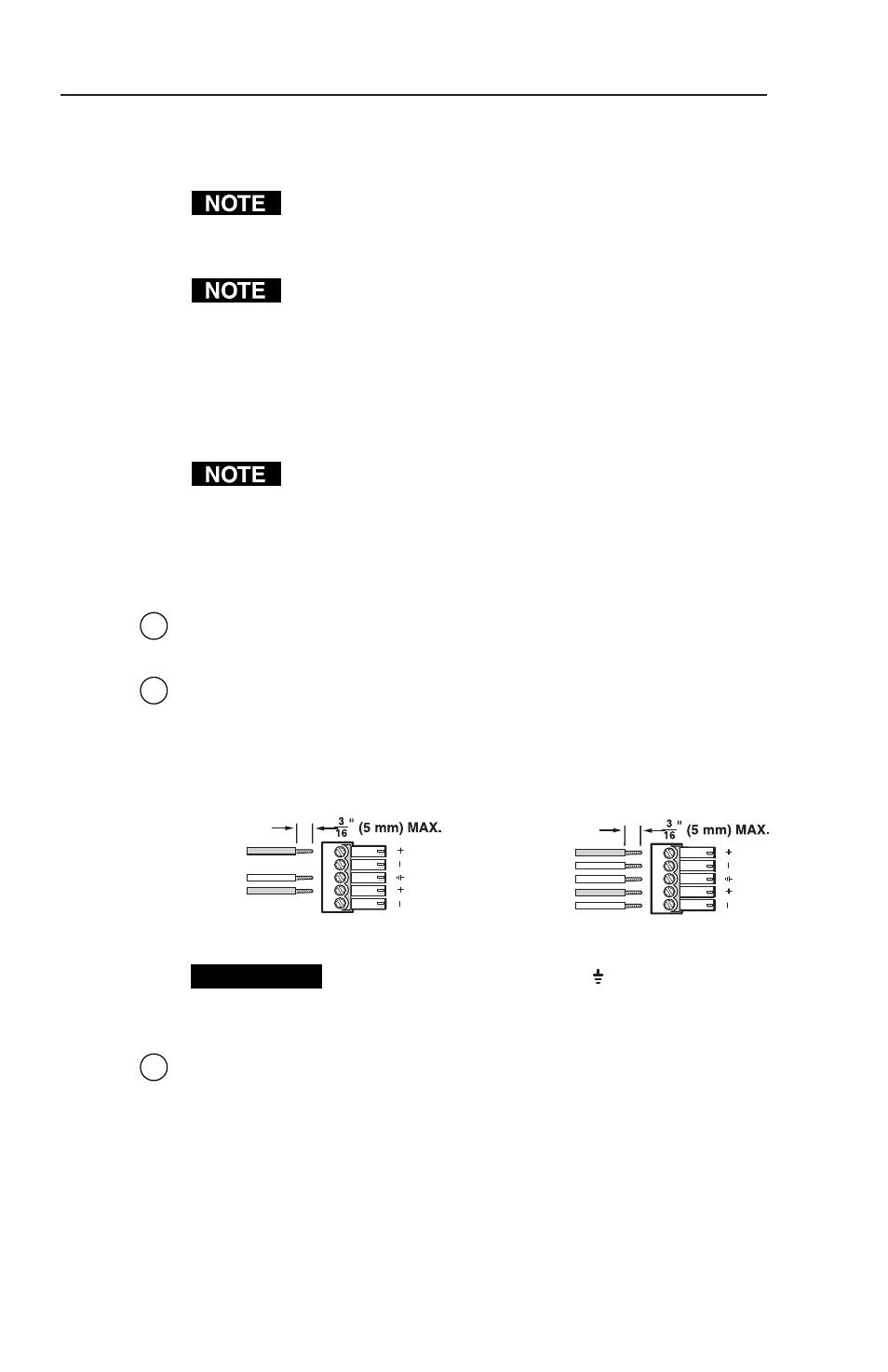
The ideal length of exposed (stripped) copper wire
for the blue connector is 3/16" (5 mm).
2
Power LED
— Lights green to indicate that the BUC 102 has
power.
3
Bal/Unbal output connector
— The balanced/unbalanced
stereo output to an amplifier from the 5-pole 3.5 mm captive
screw connector is controlled by the front panel gain adjustment
screws (see “Front Panel Features” in this chapter). Wire the
connector as shown below.
Unbalanced Output
Balanced Output
Tip
NO GROUND HERE
Sleeve (s)
Tip
NO GROUND HERE
Tip
Ring
Sleeve (s)
Tip
Ring
LR
LR
CAUTION
Connect the sleeve to ground ( ). Connecting the
sleeve to a negative (-) terminal will damage the
audio output circuits.
4
Bal/Unbal input connector
— The balanced/unbalanced stereo
input is wired to a 5-pole 3.5 mm captive screw connector. Wire
the connector as shown in the following illustration.