Rear panel features and cabling, Caution, Buc 102 • installation and operation – Extron Electronics BUC 102 User Manual
Page 11: Figure 2 — buc 102 rear panel
BUC 102 • Installation and Operation
Rear Panel Features and Cabling
BUC 102
AUDIO
BAL/UNBAL
CONVERTER
POWER
12V
0.2A MAX
L
R
BAL/UNBAL OUTPUTS
L
R
BAL/UNBAL INPUTS
SPARE
ON
BAL
UNBAL
1 2
1
3
2
4
5
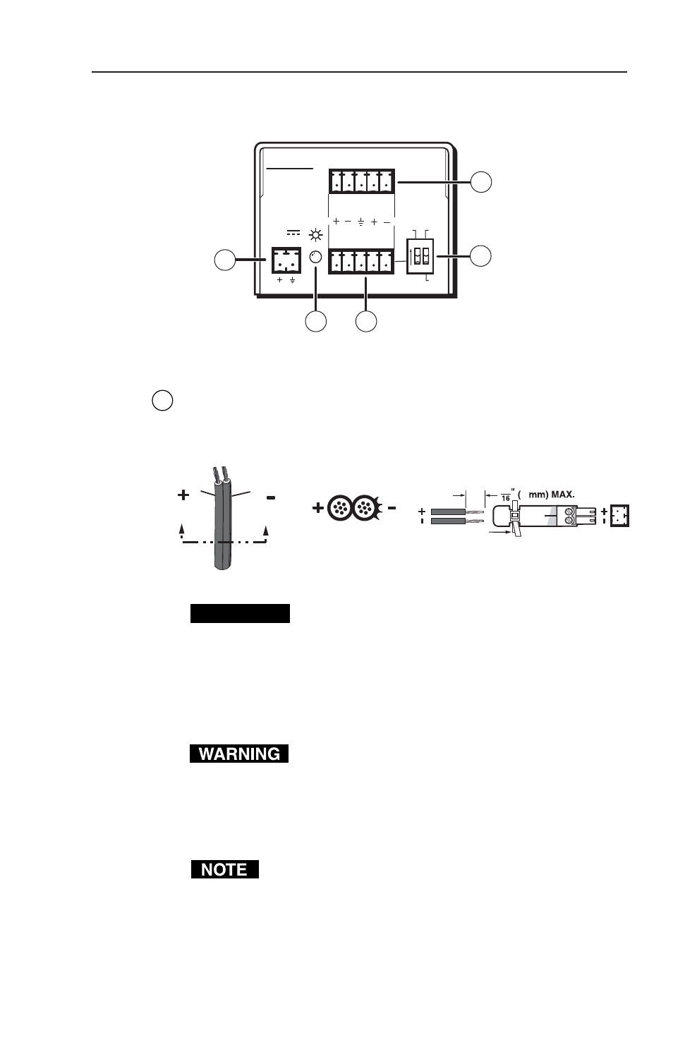
Figure 2 — BUC 102 rear panel
1
Captive screw power input connector —
Connect the included
12 VDC external power supply into the 2-pole 3.5 mm captive
screw connector. Be careful to observe the correct polarity.
Captive Screw
Connector
Tie Wrap
Power Supply
Output Cord
Ridges
Smooth
A
A
SECTION A–A
5
3
CAUTION
When connecting the power supply, voltage
polarity is extremely important. Applying power
with incorrect voltage polarity could damage the
power supply and the BUC 102. Identify the power
cord negative (ground) lead by the ridges on the
side of the cord or a black heat shrink wrapping
around it.
The two power cord wires must be kept separate
while the power supply is plugged in. Remove
power before wiring.
To verify the polarity before connection, check the no load
power supply output with a voltmeter.
Your BUC 102 may have shipped with a blue captive
screw connector. This blue connector can be plugged
into either a blue or an orange power receptacle.
The ideal length of exposed (stripped) copper wire
for the blue connector is 3/16" (5 mm).
7