John Wood Envirosense Power Vent User Manual
Page 22
22
8. Take the end of the tube at the bottom of the floor and route it to
a suitable drain. This will provide an area where the condensate
can drain without affecting the area around the appliance.
9. Once installed along with the rest of the vent configuration, make
sure to operate the unit through at least one heat up cycle to
ensure there is no leakage around the hose barb or any joints
of the VAA or vent pipe system.
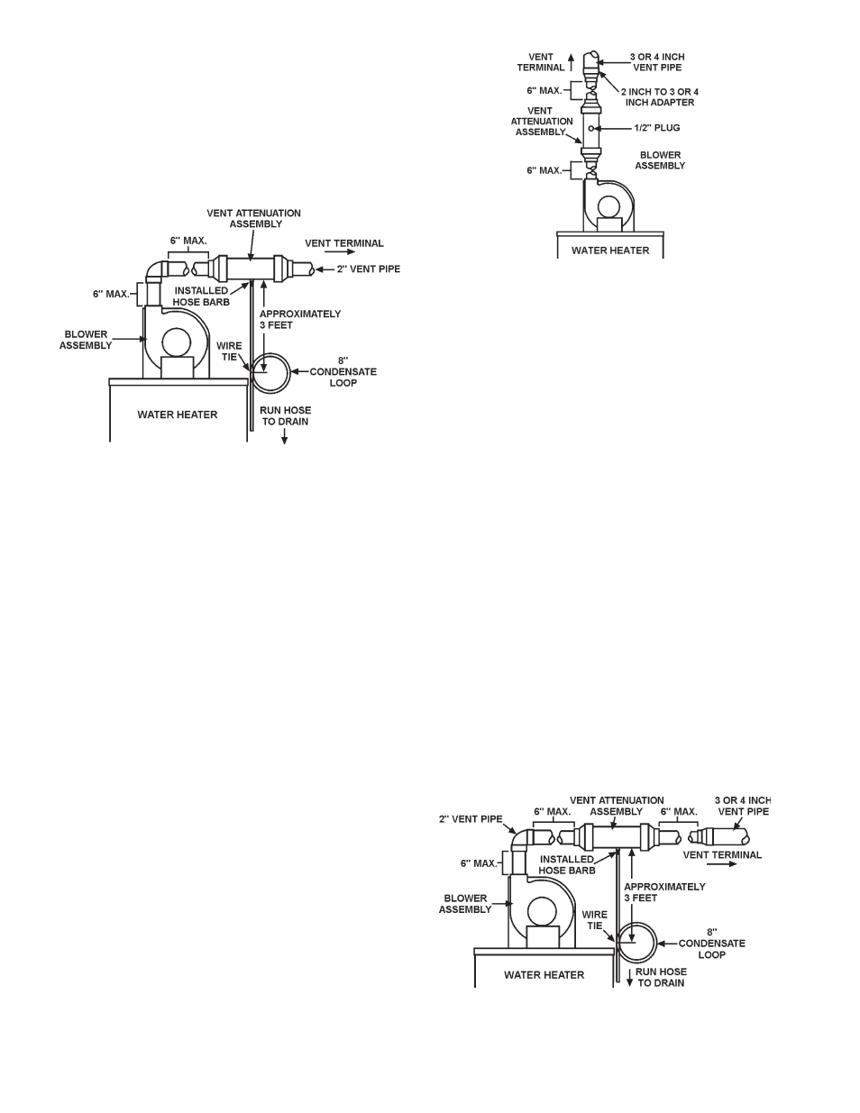
FIGURE 23: Typical Horizontal Installation
Installation for VAA with 3 & 4 inch Pipe for Vertical Vent
Some applications may require the use of 3 or 4 inch vent pipe for
longer vent lengths. Please refer to the Figure 24 as you review these
instructions. Refer back to the vertical VAA installation steps but with
the following changes to the vent construction.
3 inch vent (Vertical VAA Installations)
The VAA is designed to accommodate only 2 inch vent pipe. The
installer must use 2 inch vent pipe between the blower assembly and
the inlet into the VAA. On the outlet side of the VAA, a short run of 2 inch
vent pipe is required. Each of the short pieces of 2 inch pipe entering
and exiting the VAA must not exceed 6 inches (15 cm) in length. From
this point on, a 2 inch to 3 inch adapter may be used. From the 2 inch
to 3 inch adapter, the installer may use up to 65 equivalent feet (19.8
m) of pipe, see Figure 24 for typical installation.
4 inch vent (Vertical VAA Installations)
The VAA is designed to accommodate only 2 inch vent pipe. The
installer must use 2 inch vent pipe between the blower assembly
and the inlet into the VAA. On the outlet side of the VAA, a short
run of 2 inch vent pipe is required. Each of the short pieces of 2
inch pipe entering and exiting the VAA must not exceed 6 inches
(15 cm) in length. From this point on, a 2 inch to 4 inch adapter
may be used. From the 2 inch to 4 inch adapter, the installer may
use up to 128 equivalent feet (39.0 m) of pipe, see Figure 24 for
typical installation.
remember to operate the unit for at least one heat cycle to
ensure there are no air leaks in the vent joints of the vaa and
the vent pipe system. Air leaks will allow flue gas by-products to
disseminate into the room creating an unsafe environment and
could cause illness, asphyxiation and/or even death.
FIGURE 24: Typical Installation for Vertical Vent with 3 or 4 inch Pipe
Installation of VAA with 3 & 4 inch Pipe for Horizontal Vent
Some applications may require the use of 3 or 4 inch vent pipe for
longer vent lengths. Please refer to the Figure 25 as you review these
instructions. Refer back to the horizontal VAA installation steps but
with the following changes to the vent construction.
3 inch vent (Horizontal VAA Installations)
The VAA is designed to accommodate only 2 inch vent pipe. The
installer must use 2 inch vent pipe between the blower assembly and
the inlet into the VAA. On the outlet side of the VAA, a short run of 2
inch vent pipe is required. From this point on, a 2 inch to 3 inch adapter
may be used. From the 2 inch to 3 inch adapter, the installer may use
up to 52 equivalent feet (15.8 m) of pipe. This is 8 equivalent feet (2.4
m) less than the original 60 equivalent feet (18.3 m) specified with
one elbow due to the 2 inch elbow instead of a 3 inch elbow required
for the vent from the blower to the inlet of the VAA, see Figure 25 for
typical installation.
4 inch vent (Horizontal VAA Installations)
The VAA is designed to accommodate only 2 inch vent pipe. The
installer must use 2 inch vent pipe between the blower assembly and the
inlet into the VAA. On the outlet side of the VAA a short run of 2 inch vent
pipe is required. From this point on, a 2 inch to 4 inch adapter may be
used. From the 2 inch to 4 inch adapter, the installer may use up to 102
equivalent feet (31.1 m) of pipe. This is 18 equivalent feet (5.5 m) less than
the original 120 equivalent feet (36.6 m) specified with one elbow due to
the 2 inch elbow instead of a 4 inch elbow required for the vent from the
blower to the inlet of the VAA, see Figure 25 for typical installation.
remember to operate the unit for at least one heat cycle to ensure
there are no air leaks in the vent joints of the vaa and the vent pipe
system. Air leaks will allow flue gas by-products to disseminate
into the room creating an unsafe environment and could cause
illness, asphyxiation and/or even death.
FIGURE 25: Typical Installation for Horizontal Vent with 3 or 4 inch