Service instructions, Dealer servicing – Bell & Gossett P86109C Close Coupled Centrifugal Pumps User Manual
Page 6
SERVICE INSTRUCTIONS
1. Close valves on suction and discharge sides of pump. (If no
valves have been installed, it will be necessary to drain the
system.)
2. Remove motor foot capscrews. Loosen volute capscrews,
do not remove them. Use capscrews in the jack screw
holes. Start to remove the pump assembly from the volute.
3. Remove seal flushing tube, if used.
Remove the volute capscrews and remove the pump
assembly from the volute.
4. Remove the impeller capscrew, lock washer and washer.
Remove the impeller.
5. Remove the rotating portion of the seal, use a screwdriver
to loosen the rubber ring.
6. Remove the seal insert along with the insert gasket.
7. Thoroughly clean the shaft sleeve and the coverplate seal
cavity. Inspect for surface damage like pitting, corrosion,
nicks or scratches. Replace if necessary.
8. Lubricate the shaft sleeve and coverplate seal cavity with
soapy water. (Do not use petroleum lubricant.) Install a new
cup gasket and a new seal insert with indentation side
down into the cup.
9. Slide a new rotating seal assembly onto the shaft sleeve.
With a screwdriver push on the top of the compression ring
until the seal is tight against the seal insert. Install seal
spring.
10. Install impeller, impeller washer, lock washer and capscrew,
then tighten capscrew (per torque chart).
11. Install new volute gasket then install pump assembly into
volute. Tighten volute capscrews (per torque chart). Install
seal flushing tube, if used. Install motor foot capscrews and
tighten. Install drain plug, close drain valve.
12. Open isolation valves, inspect pump for leaks, if not leaking
return pump to service.
CAUTION: Extreme Temperature Hazard
Check surfaces for extreme temperatures, allow
pump temperatures to reach acceptable level before pro-
ceeding. Open drain valve, do not proceed until liquid stops
coming out of drain valve. If liquid does not stop flowing
from drain valve, isolation valves are not sealing and should
be repaired before proceeding. After liquid stops flowing
from drain valve leave drain valve open and continue.
Remove the drain plug located on the bottom of the pump
volute. Do not reinstall plug or close drain valve until
reassembly is completed.
Failure to follow these instructions could result in injury or
property damage.
WARNING: Unexpected Startup Hazard
Disconnect and lock out power before servicing.
Failure to follow these instructions could result in serious
personal injury or death.
CAUTION: Make certain the internal pressure is
relieved before continuing.
Failure to follow these instructions could result in injury or
property damage.
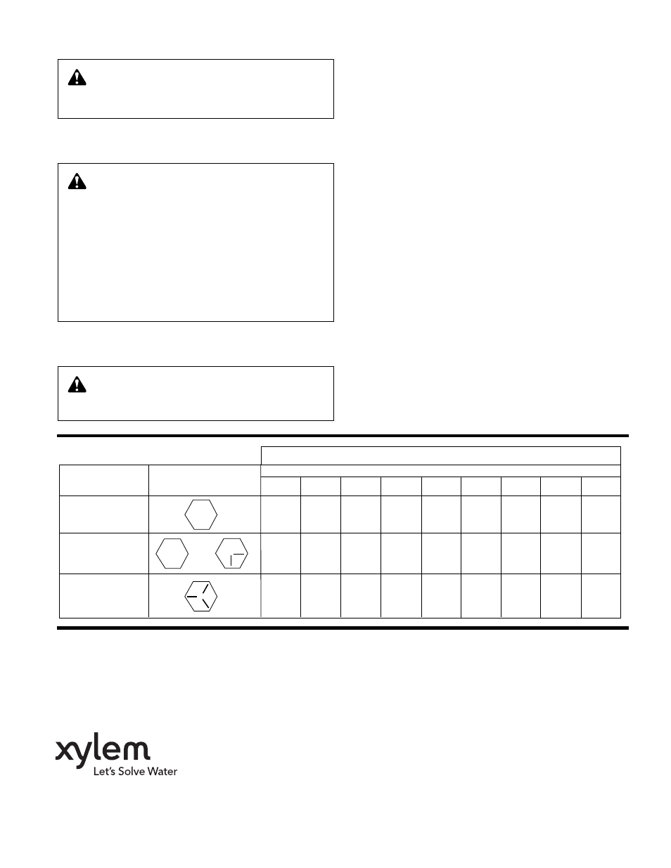
Capscrew
Head
Capscrew Diameter
Type
Marking
1
/
4
5
/
16
3
/
8
7
/
16
1
/
2
5
/
8
3
/
4
7
/
8
1
SAE Grade 2
6
13
25
38
60
20
190
210
300
Brass
4
10
17
27
42
83
130
200
300
Stainless Steel
or
SAE Grade 5
10
20
35
60
90
180
325
525
800
DEALER SERVICING
If trouble occurs that cannot be rectified contact your local
representative. He will need the following information in order to
give you assistance.
1. Complete nameplate data of pump and motor.
2. Suction and discharge pipe pressure gauge readings.
3. Ampere draw of the motor.
4. A sketch of the pump hook-up and piping.
CAPSCREW TORQUE (FOOT-POUND)
Xylem Inc.
8200 N. Austin Avenue
Morton Grove, Illinois 60053
Phone: (847) 966-3700
Fax: (847) 965-8379
www.xyleminc.com/brands/bellgossett
Bell & Gossett is a trademark of Xylem Inc. or one of its subsidiaries.
© 2013 Xylem Inc. P86109C February 2013