Installation, Rotation, Piping – Bell & Gossett P86109C Close Coupled Centrifugal Pumps User Manual
Page 4: Pump insulation
4
INSTALLATION
This pump is built to provide years of service if installed prop-
erly and attached to a suitable foundation. A base of concrete
weighing 2
1
/
2
times the weight of the pump is recommended.
(Check the shipping ticket for pump weight.)
If possible, tie the concrete pad in with the finished floor.
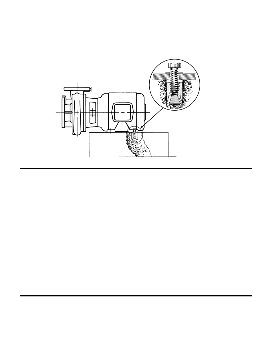
To facilitate easy servicing, some type of expansion fitting
should be utilized. The female portion should be inserted into a
suitable hole in the floor so that its top surface is flush with the
floor surface. Thus, when the hold-down bolts are removed, the
motor can be removed by sliding it back from the pump. (See
Figure 5)
ROTATION
Pump rotation is clockwise when viewed from back of the motor.
An arrow is provided to show direction of rotation.
PIPING
Always install a section of straight pipe between the suction
side of the pump and first elbow. This reduces turbulence of the
suction by straightening out the flow of liquid before it enters the
pump. The length should be equal to five times the diameter of
the pipe.
Be sure to eliminate any pipe-strain on the pump. Support the
suction and discharge pipes independently by use of the pipe
hangers near the pump. Line up the vertical and horizontal
piping so that the bolt-holes in the pump flanges match the bolt-
holes in the pipe flanges. DO NOT ATTEMPT TO SPRING THE
SUCTION OF DISCHARGE LINES INTO POSITION. Bearing
wear will result if suction or discharge lines are forced into posi-
tion. The code for Pressure Piping (A.S.A.B.31.1) lists many
types of supports available for various applications.
As a rule, ordinary wire or band hangers are not adequate to
maintain alignment. It is very important to provide a strong, rigid
support for the suction and discharge lines.
Where considerable temperature changes are anticipated,
fittings for absorption expansion should be installed in the
system in such a way as to avoid strain on the pump.
On an open system with a suction lift, use a foot-valve of equal
or greater area than the pump suction piping. Prevent clogging
by using a strainer at the suction inlet next to the foot-valve. The
strainer should have an area three times that of the suction pipe
with a mesh hole diameter of no less than
1
/
4
".
When using an isolation base, flexible piping should be used on
both the suction and discharge sides of the pump.
NOTES
1. The pipeline should have isolation valves around the pump
and have a drain valve in the suction pipe.
2. When installing the suction and discharge connection to a
threaded pump housing the use of PTFE tape sealer or a
high quality thread sealant is recommended.
PUMP INSULATION
When insulating your pump, ensure that the coverplate vent slots
and the motor remain uncovered.
FIG. 5