Piping checklist – Xylem P2000799B Series e-90 Close-Coupled In-Line Centrifugal Pumps User Manual
Page 12
Mode of discharge
You can install this pump to discharge either vertically or horizontally. The arrow on the
pump body must point in the direction of the flow.
You can install the pump with the motor either vertical or horizontal. Do not install the
motor below the pump body.
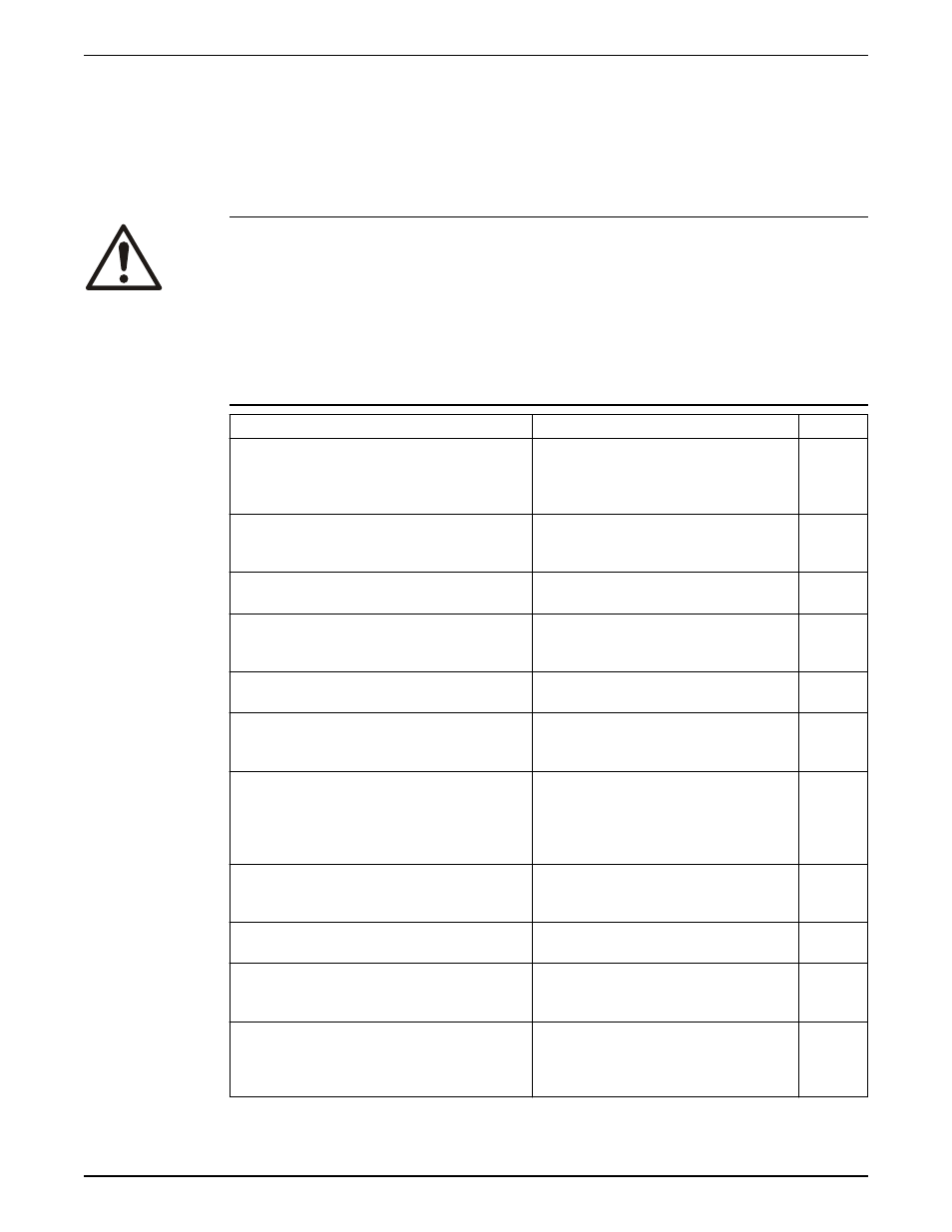
Piping checklist
WARNING:
• The heating of water and other fluids causes volumetric expansion. The associated
forces can cause the failure of system components and the release of high-
temperature fluids. In order to prevent this, install properly sized and located
compression tanks and pressure-relief valves. Failure to follow these instructions can
result in serious personal injury or death, or property damage.
• Avoid serious personal injury and property damage. Make sure that the flange bolts
are adequately torqued.
• Never force piping to make a connection with a pump.
Check
Explanation/comment
Checked
Check that a section of straight pipe, with a length that
is five times its diameter, is installed between the
suction side of the pump and the first elbow, or that a
B&G Suction Diffuser is installed.
This reduces suction turbulence by
straightening the flow of liquid before it enters
the pump.
Check that the suction and discharge pipes are
supported independently by use of pipe hangers near
the pump .
This eliminates pipe strain on the pump .
Check that there is a strong, rigid support for the
suction and discharge lines.
As a rule, ordinary wire or band hangers are not
adequate to maintain proper alignment.
For pumps with flanges, check that the bolt holes in
the pump flanges match the bolt holes in the pipe
flanges.
—
Check that the suction or discharge lines are not
forced into position.
Bearing wear will result if suction or discharge
lines are forced into position.
Check that fittings for absorbing expansion are
installed in the system when considerable
temperature changes are expected.
This helps to avoid strain on the pump.
Check that you have a foot valve of equal or greater
area than the pump suction piping when you use in
an open system with a suction lift.
Prevent clogging by using a strainer at the
suction inlet next to the foot valve. Make sure
that the strainer has an area three times that of
the suction pipe with a mesh hole diameter of
no less than 0.25 in. (0.64 cm).
Check that a B&G Triple Duty
®
valve is installed in the
discharge line.
This valve serves as a check valve that protects
the pump from water hammer, and serves as an
isolation valve for servicing and for throttling.
Check that the pipeline has isolation valves around
the pump and has a drain valve in the suction pipe.
—
Use PTFE tape sealer or a high quality thread sealant
when you install the suction and discharge
connections to a threaded pump housing.
—
On an open system, check that the end of the suction
pipe is at least 3 ft. below the surface of the water in
the suction well.
This prevents air from being drawn into the
pump. Avoid air pockets in the suction line and
make sure that each section of the suction pipe
is air tight.
Installation
10
Series e-90 Close-Coupled In-Line Centrifugal Pumps Installation, Operation, and Maintenance Manual