A-100nv, Page 9, 1mode – Xylem A-100NV DIGITAL PERISTALTIC PUMPS User Manual
Page 9
Page 9
6.0 How To Operate The A-100NV
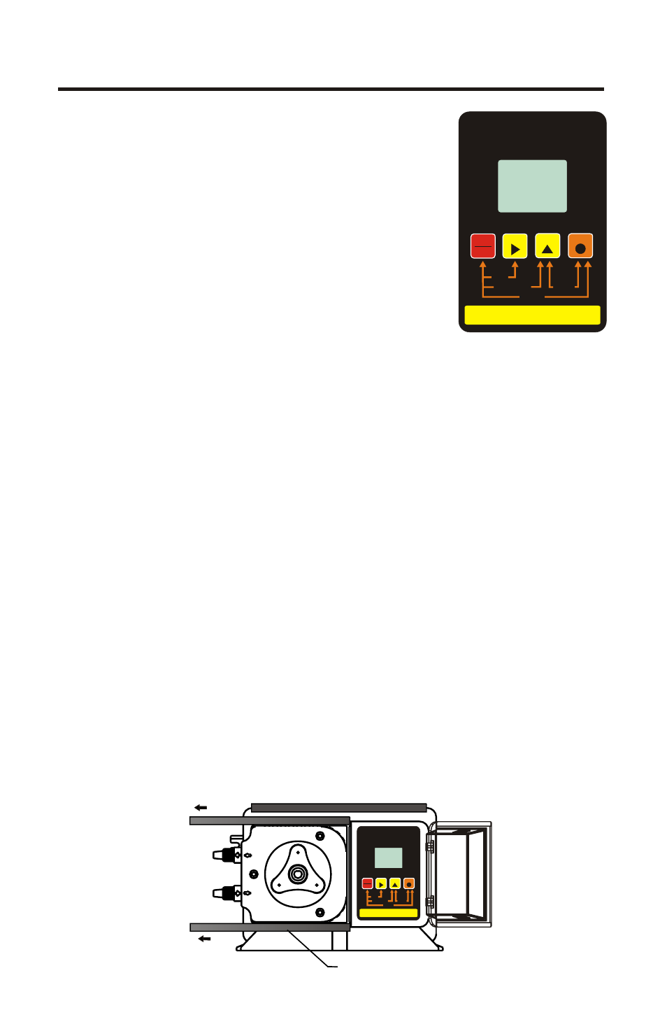
6.1 Description of Pump Output
Adjustment Controls
- Open the control
panel door by sliding the upper and lower slide
clamps to the left.
! RUN/STANDBY Button -
4 Press to start and stop the pump. The ARROW
next to the word RUN will light when in the run
mode. The ARROW next to the word STAND-BY
will blink when in the stand-by mode.
4 Press to clear ALARM.
4 When pressed with the FIELD Button, initiates a 99 second prime cycle
which temporarily overrides the mode setting and runs the pump motor at
100% speed. The ARROW next to the word PRIME will blink.
4 When pressed with the DIGIT button, resets the 500 hour service warning
timer to zero.
4 When pressed with the MODE button, initiates the programming mode.
The ARROW next to the word PROGRAM will blink.
! FIELD Button -
4 In the programming mode, selects the digit to be changed.
4 When pressed with the DIGIT button, initiates the Flow Verification
Sensor feature and allows programming the alarm delay from 1-256
seconds.
! DIGIT Button -
4 In the programming mode, increases the selected digit.
4 When pressed with the MODE Button, toggles the display from % motor
speed to input signal value.
! MODE Button -
4 Used to select one of four operating modes.
Mode 1 - Manual Adjustment (external input disabled)
Mode 2 - 4-20mA input
Mode 3 - 0-10VDC input
Mode 4 - Frequency (Hz) input
SLIDE CLAMP
RUN
STANDBY
RUN
FIELD
DIGIT
MODE
PROGRAM
STAND-BY
PRIME
MINIMUM
MAXIMUM
INPUT MODES
1 - MANUAL
2 - 4-20mA
3 - 0-10VDC
4 - PULSE (Hz)
PROGRAM
RESET SERVICE
PRIME
DISPLAY
VARIABLE SPEED PUMP
% SPEED
1
MODE
VDC
SERVICE
1000
ALARM
mA
Hz
RUN
STANDBY
RUN
FIELD
DIGIT
MODE
PROGRAM
STAND-BY
PRIME
MINIMUM
MAXIMUM
INPUT MODES
1 - MANUAL
2 - 4-20mA
3 - 0-10VDC
4 - PULSE (Hz)
PROGRAM
RESET SERVICE
PRIME
DISPLAY
VARIABLE SPEED PUMP
% SPEED
1
MODE
VDC
SERVICE
1000
ALARM
mA
Hz
A-100NV