F-1000, 6 how to install molded pvc tee fittings (te), 5 installing the molded in-line fitting (mi) – Xylem F1000 PADDLEWHEEL FLOW METERS User Manual
Page 8: Page 8, Page 9, Fig. 9, Fig. 11, Fig. 10, Dl k h w
Body Description
3/8” MPT-std flow
1/2” MPT-std flow
3/4” MPT-std flow
1.0” MPT-std flow
3/8” MPT-low flow
1/2” MPT-low flow
Length
L
4.73”
5.09”
5.25”
5.65”
4.73”
5.09”
3/4” MPT-low flow
1.0” MPT-low flow
5.25”
5.65”
4.4
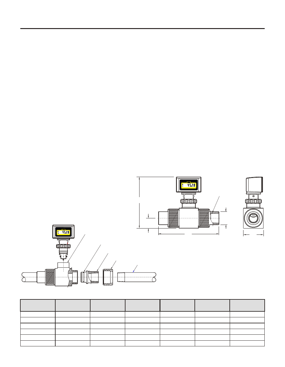
INSTALLING THE F-1000 MACHINED IN-LINE FITTING (PI)
F-1000 machined in-line fittings consist of a meter body, two pipe adapter fittings (inlet and outlet), and two
half union nuts. Pipe adapters are supplied with female American National Standard Taper Pipe Threads (NPT).
The adapters are secured to the meter body with half union nuts and sealed with Viton O-rings.
Select an area on the pipe as outlined in section 4.1.
Install the F-1000 as you would any other plastic pipe fitting. Because the F-1000 uses half union nut style
connections, the adapters can be installed on the piping system first and then secured to the meter body with
the unions.
The F-1000 can be mounted on horizontal or vertical runs of pipe. Mounting at the twelve o'clock position
on horizontal pipe is recommended. Mounting anywhere around the diameter of vertical pipe is acceptable,
however, the pipe must be completely full of water at all times. See figure 4, 5 and 6.
Be sure the inlet and outlet fittings are aligned properly. Improper alignment of the fittings will put stress on
the adapter connections and may cause leaking or fitting damage.
Do not over tighten the fittings.
Use Teflon® tape sealant only on the adapter threads. Do not use pipe dope or glue.
Be sure the inlet and outlet plumbing is properly secured. The F-1000 is not designed to support the weight
of related piping. Improperly supported pipes will put stress on the adapter connections and may cause
leaking or fitting damage.
!
!
!
!
!
!
!
4.6
HOW TO INSTALL MOLDED PVC
TEE FITTINGS (TE)
Select an area on the pipe as outlined in section 4.1.
Remove the F-1000 sensor from the tee fitting. Do not glue the
TEE while the sensor is installed.
Install the F-1000 tee fitting as you would any other plastic
pipe solvent weld (glue) fitting. Do not use too much glue.
Excessive glue may create a disturbance in the flow stream
which will effect the accuracy of the meter.
The F-1000 can be mounted on horizontal or vertical runs of
pipe. Mounting at the twelve o'clock position on horizontal
pipe is recommended. Mounting anywhere around the diame-
ter of vertical pipe is acceptable, however, the pipe must be
completely full of water at all times. See figure 4, 5 and 6.
Install the F-1000 sensor. Be sure two O-rings are located on
the sensor body. The O-rings have been lubricated at the
factory with silicone oil. Push the sensor assembly into the
saddle with a twisting motion. The notch on the sensor body
must fit into the slot on the saddle. Be sure the sensor is fully
inserted into the saddle. HAND TIGHTEN the union nut.
!
!
!
!
!
F-1000
Page 8
F-1000
Page 9
F-1000-RT
Rate -
Totalizer
®
BLUE-WHITE INDUSTRIES
GALLONS PER MINUTE
Machined in-line body
O-ring
Machined adapter with FPT
Union nut
Pipe
Fig. 9
H
Nominal
Pipe Size
L
Fig. 11
Tee Fitting
Height
H
5.38”
5.38”
5.57”
5.57”
5.29”
5.29”
5.38”
5.57”
Nominal Pipe
Size
3/8”
1/2”
3/4”
1.0”
3/8”
1/2”
3/4”
1.0”
1”
4”
6”
1-1/2”
4-1/2”
6-5/8”
2”
4-3/4”
7-1/8”
Nominal Pipe
Size
Length
L
Height
H
Fig. 10
Molded in-line body
with M P T
Pipe
H
L
F-1000-RT
Rate -
Totalizer
®
BLUE-WHITE INDUSTRIES
GALLONS PER MINUTE
F/NPT - Female
Pipe Threads
D
L
K
H
W
F-1000-RT
Rate -
Totalizer
®
BLUE-WHITE INDUSTRIES
GALLONS PER MINUTE
F-1000-RT
Rate -
Totalizer
®
BLUE-WHITE INDUSTRIES
GALLONS PER MINUTE
4.5
INSTALLING THE MOLDED IN-LINE FITTING (MI)
All molded in-line (MI) fittings have male American National Standard Taper Pipe Threads (MPT).
Select an area on the pipe as outlined in section 4.1.
Install the F-1000 as you would any other plastic pipe fitting. Be sure the inlet and outlet fittings are aligned
properly. Improper alignment of the fittings will put stress on the adapter connections and may cause
leaking or fitting damage. Do not over tighten the fittings. Use Teflon® tape sealant only on the adapter
threads.
The F-1000 can be mounted on horizontal or vertical runs of pipe. Mounting at the twelve o'clock position
on horizontal pipe is recommended. Mounting anywhere around the diameter of vertical pipe is acceptable,
however, the pipe must be completely full of water at all times. See figure 4, 5 and 6.
Be sure the inlet and outlet plumbing is properly secured. The F-1000 is not designed to support the weight
of related piping. Improperly supported pipes will put stress on the adapter connections and may cause
leaking or fitting damage.
!
!
!
!
Nominal Pipe Size
3/8”
1
/2”
3/4”
1.0”
1-1/2”
2.0”
Pipe Threads
Size
3/8” - F/NPT
1
/2” - F/NPT
3/4” - F/NPT
1.0” - F/NPT
1-1/2” - F/NPT
2.0” - F/NPT
Overall Length
L
7.4” (188 mm)
7.4” (188 mm)
7.4” (188 mm)
7.4” (188 mm)
9.4” (239 mm)
11.4” (290 mm)
Overall Height
H
6.3” (159 mm)
6.3” (159 mm)
6.3” (159 mm)
6.3” (159 mm)
6.6” (167 mm)
7.1” (180 mm)
Center Height
K
1.22 “ (31 mm)
1.22 “ (31 mm)
1.22 “ (31 mm)
1.22 “ (31 mm)
1.70” (43 mm)
2.00” (51 mm)
Adapter O.D.
D
1.60” (40.6 mm)
1.60” (40.6 mm)
1.60” (40.6 mm)
1.60” (40.6 mm)
2.50” (63.5 mm)
3.08” (78.2 mm)
Body Width
W
2.45” (62 mm)
2.45” (62 mm)
2.45” (62 mm)
2.45” (62 mm)
2.5” (63 mm)
3.0” (76 mm)