H-3531 – Xylem H-3521 User Manual
Page 54
B-2 Modbus Protocol
H-3531
B.4 Holding Registers
There are 25 holding registers in the H-3531 FlashLite™, some are Read/Write registers and some
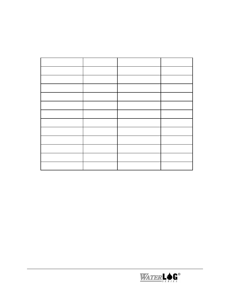
are Read Only registers. The user configurable settings are found in the Holding Registers. Table
2 below shows the contents on the Holding Registers followed by a description of each register.
Table 2 - Holding Registers
Info in Register
Start Address
# of 16-bit Registers
Data Type
ID String
0 / “0000"
17
Char String
Modbus Address
18 / “0012"
1
Short Integer
Stage Units Select
19 / “0013"
1
Short Integer
***Reserved***
20 / “0014"
1
Short Integer
Modbus Baudrate
21 / “0015"
1
Short Integer
Parity
22 / “0016"
1
Short Integer
User Stage Offset
23 / “0017"
4
IEEE F P.
User Stage Slope
27 / “001B”
4
IEEE F.P.
User Stage Offset
31 / “001F"
2
IEEE F.P.
User Stage Slope
33 / “0021”
2
IEEE F.P.
Set Current Stage
35 / “0023”
4
IEEE F.P.
Set Current Stage
39 / “0027”
2
IEEE F.P.
B.4.0 ID String(RO)
The first registers in the Holding Registers are the ID string registers, this is the same ID
string that the SDI-12 ID command returns. Refer to SDI-12 ID command to see details of
the response. The ID string consists of 17, 16-bit registers. These registers can be read
separately but to get the full ID string the user must read all 17-registers at once. These
registers are RO (read only) registers. As shown in Table 2 the response to reading the ID
string is sent as a ASCII character string. Example, to read the full ID string the host must
send the request as follows: “aa0300000011crcc”
H-3531 FlashLite™ Response: “113 DAA H-3531001S#000000V011
B.4.1 Modbus Address(R/W)
This holding register allows the user to change the Modbus address of the H-3531
FlashLite™. The programmable address range is: 1 - 247. The assigned Modbus address
factory default is: ‘1'. Address “0" is reserved for the broadcast address meaning that all
Modbus sensors will respond to address “0".