Safety instructions, Typical installation, Danger – Xylem IM182 Balanced Flow User Manual
Page 3
3
1: SAFETY INSTRUCTIONS
TO AVOID SERIOUS OR FATAL PERSONAL INJURY
OR MAJOR PROPERTY DAMAGE, READ AND
FOLLOW ALL SAFETY INSTRUCTIONS IN MANUAL
AND ON EQUIPMENT.
THIS MANUAL IS INTENDED TO ASSIST IN THE
INSTALLATION AND OPERATION OF THIS UNIT AND
MUST BE KEPT WITH THE UNIT.
This is a SAFETY ALERT SYMBOL.
When you see this symbol on the pump,
the controller or in the manual, look for
one of the following signal words and
be alert to the potential for personal
injury or property damage.
Warns of hazards that WILL cause
serious personal injury, death or major
property damage.
Warns of hazards that CAN cause serious
personal injury, death or major property
damage.
Warns of hazards that CAN cause
personal injury or property damage.
NOTICE:
INDICATES SPECIAL
INSTRUCTIONS WHICH ARE
VERY IMPORTANT AND MUST BE
FOLLOWED.
THOROUGHLY REVIEW ALL INSTRUCTIONS
AND WARNINGS PRIOR TO PERFORMING ANY
WORK ON THIS CONTROLLER.
MAINTAIN ALL SAFETY DECALS.
DANGER
WARNING
CAUTION
This controller is not designed for use
around swimming pools, open bodies of
water, hazardous liquids, or where flammable gases exist.
Do not use GFCI input power. This will
cause nuisance faults.
Disconnect and lockout electrical power
before installing or servicing any
electrical equipment.
ELECTROCUTION HAZARD.
CONTROLLER INPUT GROUND
TERMINAL (GND) AND ALL EXPOSED METAL
PIPING, INCLUDING PRESSURE TRANSDUCER
CASE, MUST BE CONNECTED TO THE SERVICE
ENTRANCE GROUND TERMINAL.
All electrical work must be performed
by a qualified technician. Always follow
the National Electrical Code (NEC), or the Canadian
Electrical Code, as well as all local, state and provincial
codes. Code questions should be directed to your local
electrical inspector. Failure to follow electrical codes and
OSHA safety standards may result in personal injury or
equipment damage. Failure to follow manufacturer’s
installation instructions may result in electrical shock,
fire hazard, personal injury or death, damaged
equipment, unsatisfactory performance, and may void
manufacturer’s warranty.
NOTICE: Some installations pull a vacuum on the
transducer when the system is drained. The new controller
is designed to protect against up to 17” Hg. of vacuum
on the transducer. An optional Gauge Guard, order
no. 6K210, will protect the transducer from a vacuum
condition.
WARNING
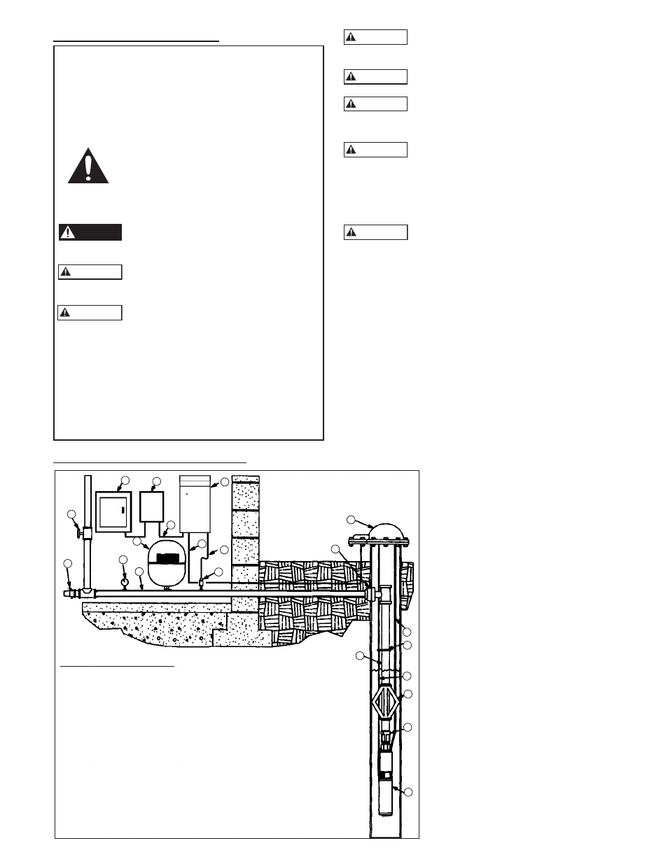
PARTS DESCRIPTION:
1) Pump and Motor
10) Power Supply Cable
2) Check Valve (built-in
11) Service Entrance
on some models)
12) Pressure Sensor Cable
3) Torque Arrestor (optional)
with drip loop
4) Pump Power Cable
13) Diaphragm Tank
with Splice Kit
14) Pressure Transducer
5) Electrical Tape
15) Pressure Gauge
(Cable to Pipe)
16) Relief Valve
6) Safety Rope (optional)
17) Shut-Off Valve
7) Well Cap / Seal
18) Drop Pipe
8) Pitless Adapter
19) Lateral Pipe
9) Controller
20) Electrical Disconnect
17
16
9
15
11
10
12
13
14
4
8
7
6
5
4
3
2
1
TYPICAL INSTALLATION
TYPICAL INSTALLATION
18
19
20
WARNING
WARNING
WARNING
1: SAFETY INSTRUCTIONS
WARNING