Xylem IM182 Balanced Flow User Manual
Page 11
11
Table 6: Fault Blink Codes
(continued on next page)
RED LIGHT CODES
Flashes
Controller Status
Description
3 Blinks
Sensor Fault
This fault can be caused by:
• Disconnected sensor. Disconnect sensor from sensor cable connector and
reconnect to ensure a good connection.
• Disconnected sensor cable lead inside the controller. Check for loose wires
where the sensor cable connects to the circuit board by tugging on each wire.
• Broken wire in the sensor cable.
• Miswired sensor cable. Check that the wires are connected to the correct ter-
minals on the sensor connector. The correct location of the wires is indicated
on the circuit board. B=Black, R=Red, W=White.
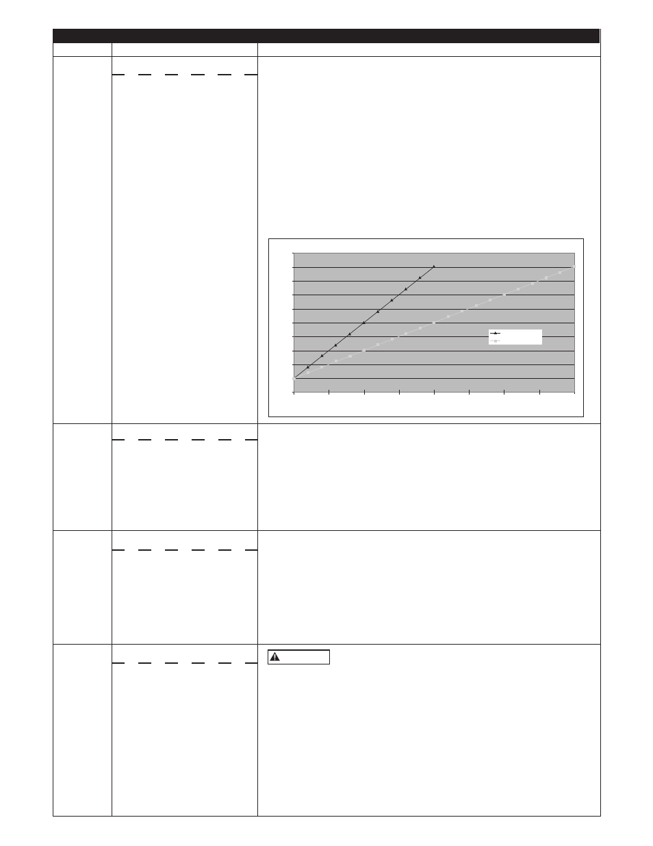
• Failed sensor. With the sensor cable connected to the circuit board, measure
the DC voltage between the black and white wires of the sensor cable at
the sensor connector. The voltage measured should be between 0.5Vdc and
4.5Vdc depending on the system pressure, see chart below.
• A vacuum on the sensor (transducer) of 17" Hg or more will cause a sensor
fault, eliminate the vacuum.
4 Blinks
Pump or Motor Bound
This fault can be caused by:
• Installing a 1Ø motor - system requires a 3Ø, 200 or 230 V motor.
• Mechanical binding from debris in pump.
• Electrical failure of the motor.
• Incorrect setting of “MOTOR OVERLOAD SETTING (SFA)” switch.
A false “bound pump” error will be displayed if the switch is set too low.
Verify the error by turning power to controller off for 1 minute and then on.
Pump/Motor must be checked if fault persists.
5 Blinks
Short Circuit
This fault can be caused by:
• Electrical failure of the motor.
• Electrical failure of wiring between controller and motor.
Verify the error by turning power to controller off for 1 minute and then on.
If error persists, motor and wiring between controller and motor must be
checked. Turn power off for 5 minutes. Remove the three motor wires from
the terminal block. Check wiring and motor for shorting phase to phase and
phase to ground. Refer to motor’s manual for information on resistance
readings.
6 Blinks
Ground Fault
This device does not provide personnel protection against
shock. This function is intended for equipment protection
only.
This fault can be caused by:
• Electrical failure of the motor
• Electrical failure of wiring between controller and motor.
• Miswiring of motor cable.
Verify the error by turning power to controller off for 1 minute and then on.
If error persists, motor and wiring between controller and motor must be
checked. Turn power off and wait 5 minutes. Remove the three motor wires
and ground wire from the terminal block. Check wiring and motor for
shorting phase to ground using a megohmmeter (“megger”). A reading less
than 200K Ohms indicates faulty insulation in the motor cable or motor.
Test each to determine fault location.
The controller will not run
if the signal from the
sensor is disconnected or out
of tolerance. The controller
will automatically restart when
the signal is within tolerance. If
fault persists contact installer.
Pressure (PSI)
Sensor Output vs. Applied Pressure
Transducer Output (V
olts DC)
100 PSI Sensor
200 PSI Sensor
0
0.5
1
1.5
2
2.5
3
3.5
4
4.5
5
0
25
50
75
100
125
150
175
200
The controller will try to restart the
motor three times before displaying
this fault. To clear the fault, turn off
power to the controller, wait 1 min-
ute, turn on power to the controller.
If fault persists contact installer.
If this fault is detected while
the pump is running, the
controller will attempt to restart
three times before displaying this
fault. To clear the fault, turn off
power to the controller, wait 1 min-
ute, turn on power to the controller.
If fault persists contact installer.
The controller will not restart
if displaying this fault. To clear
the fault, turn off power to the
controller, wait 1 minute, turn
on power to the controller. If
fault persists contact installer.
WARNING