Xylem IM244R04 SPD Plus Variable Speed Pump Control User Manual
Page 28
28
APPENDIX A: INPUT POWER
SPECIFICATIONS
(CONTINUED)
4) Power Factor Capacitor Isolation: Input
transformers are sometimes used to provide
impedance to isolate drives from line connected
power factor correction capacitors. PWM drive
inputs do not require power factor correction
capacitors as drive power factors are generally
greater than 92% and cannot be significantly
improved with power factor correction capacitors
which only correct for fundamental. However drives
should be isolated from power factor correction
capacitors by about 3 to 6% additional impedance
with respect to the drives. Line reactors can
perform this function much more cost effectively
than isolation transformers. SPD Plus drives have
either an internal 3% line reactor or an equivalent 3
to 5% bus reactor.
5) RFI/EMI Mitigation: Neither input isolation
transformers nor line or bus reactors provide good
high frequency filtering although an isolation
transformer with a static shield will provide some
RFI mitigation. If RFI/EMI mitigation is required,
an RFI/EMI filter mounted inside the drive should
be used together with all the proper wiring and
grounding techniques. Some RFI/EMI filters may
operate only on a power source with a grounded
neutral. Establishing a local neutral ground may
require the use of an input isolation transformer.
CORNER GROUNDED TN SYSTEMS
WARNING
Do not attempt to install or remove the EMC
filter screws EM1, EM3, F1 or F2 while power is
applied to the drive's input terminals.
Corner grounded TN systems are defined in the
following table. In such systems, disconnect the
internal ground connection through the EMC filter
capacitors (do this also if the grounding configuration
of the system is unknown), see SECTION 6: POWER
SUPPLY AND WIRING for details.
The EMC filter capacitors make an internal ground
connection that reduces electro-magnetic emission.
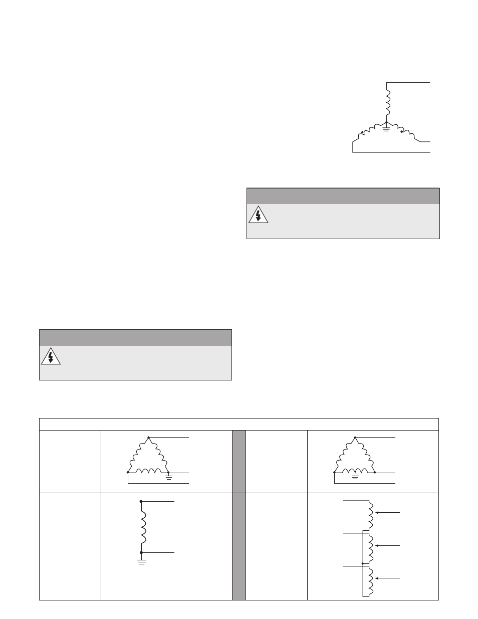
Where EMC (electro-
magnetic compatibility) is
a concern, and the system
is symmetrically grounded,
the EMC filter may be
connected. For reference,
the diagram on the right
illustrates a symmetrically
grounded TN system (TN-S
system).
FLOATING NETWORKS
WARNING
Do not attempt to install or remove the EMC
filter screws EM1, EM3, F1 or F2 while power is
applied to the drive's input terminals.
For IT systems (an ungrounded power system or
a high-resistance-grounded [over 30 ohm] power
system):
• Disconnect the ground connection to the internal
EMC filter, see SECTION 6: POWER SUPPLY AND
WIRING for details.
• Where EMC requirements exist, check for
excessive emission propagated to neighboring
low voltage networks. In some cases, the natural
suppression in transformers and cables is
sufficient. If in doubt, use a supply transformer
with static screening between the primary and
secondary windings.
• Do NOT install an external RFI/EMC filter. Using
an EMC filter grounds the input power through
the filter capacitors, which could be dangerous
and could damage the drive.
Corner Grounded TN Systems — EMC Filter must be disconnected
Grounded at
the corner of
the delta
L1
L2
L3
Grounded at
the mid point
of a delta leg
L1
L2
L3
Single phase,
grounded at an
end point
L1
N
Three phase
"Variac"
without solidly
grounded
neutral
L1
L2
L3
L1
L2
L3
L1
L2
L3