Bell & Gossett 6 71 075 115A LS Condensate Removal Pump User Manual
Page 4
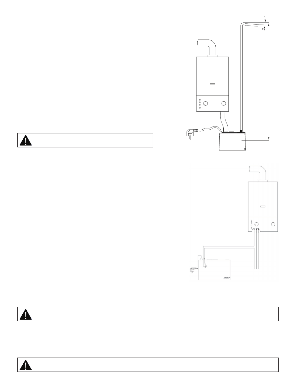
1. Condensate supply hose must be routed with a downward slope
to the LS Condensate Pump. (See Fig.5)
2. Ensure condensate supply hose is inserted deep enough into the
tank inlet so that it cannot slip out unintentionally. A second inlet
opening is available for additional hose connections.
3. For installation of the condensate drainage hose ensure hose is
inserted as far as possible onto the non-return valve. Tip: We
recommend that you also secure the hoses using hose clamps.
4. After securing hose on non-return valve, lock non- return valve by
rotating valve one quarter turn clockwise.
Electrical Connection
The LS has a 6.5 ft (2m) long mains cable with a shock-proof plug. If
the cable is not long enough, we recommend that you use an
extension lead or connect a distribution box. The mains cable is
permanently connected to the pump and cannot be removed and
replaced with a longer mains cable. The electrical connection used
must comply with the applicable standards. In particular, it must be
properly earthed and fused.
WARNING: All electrical work done may only be
performed by qualified electrical professionals.
max. 4m
4°
Fig.5
Alarm connection
The LS Condensate Pump is equipped with an alarm connection
(switching with a 15 sec delay). This allows the condensing or air
conditioning system to be switched off to prevent more condensate
being fed and the tank overflowing. If the alarm connection is to be
used, the 6.5 ft (2m) alarm connection cable must be connected as
shown in the illustration. If the cable is not long enough, we
recommend that you connect a distribution box. The alarm cable is
permanently connected to the pump and cannot be removed. If the
alarm connection is not used, the alarm cable can be cut off directly
at the pump. In order to prevent moisture penetrating into the
pump electronics, replace the original rubber cap with the hole with
the closed rubber cap provided.
Functional Testing
After installing the condensate pump, we recommend that you test
it to ensure that it functions correctly. To test the function, pour
water (approx. 0.4 l) into the tank – via the secondary inlet opening
if possible, until the activation level is reached and the pump starts.
If air in the pump causes the integrated dry-run protection to
actuate (pump deactivates, green and red operating lamp flash), add
a further 0.2 l of water and wait for one minute. The pump restarts
automatically after one minute. The LS condensate pump is now
functional.
Fig.6
L N PE
Routine Maintenance and Disassembly of LS Condensate Unit
The LS pump does not require special maintenance. However, we recommend that you remove encrustation and rinse
with clear water regularly in accordance with the occurrence of soiling. When you press in the clip, the LS can be
removed by pulling it upwards away from the mounting bracket (see exploded view illustration). Disassembly of the
condensate pump: Remove the pressure hose and non-return valve from the pump housing by turning them one
quarter turn counter-clockwise. Pull the condensate supply hose carefully out of the tank.
WARNING: The LS Condensate Pump must be disconnected from the mains power supply before maintenance
or disassembly!
WARNING: Condensate from condensing systems is aggressive. Avoid contact with residual condensate in the
tank, in the condensate supply hose or in the pressure hose!