Pam8902a, Application information – Diodes PAM8902A User Manual
Page 7
PAM8902A
Document number: DSxxxxx Rev. 1 - 3
7 of 12
February 2013
© Diodes Incorporated
PAM8902A
A Product Line of
Diodes Incorporated
Application Information
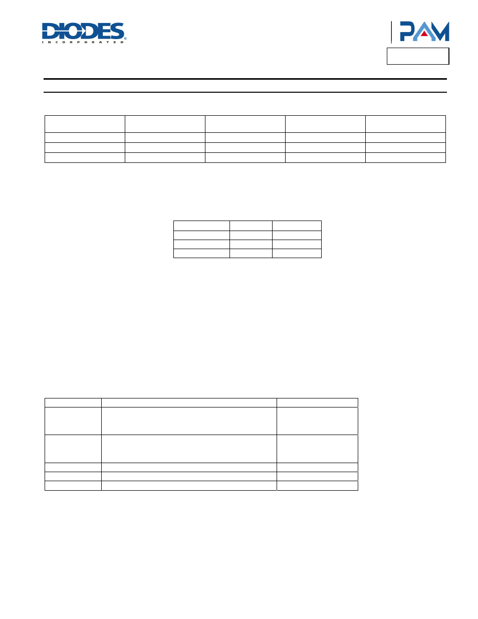
Select Boost Converter Output Voltage
The V
SET
pin sets the boost converter output voltage to 8V, 12V or 17.5V. V
SET
pin configuration table as below:
V
SET
Pin Configuration
Min Max
PVCC
Voltage
Audio Amplifier
Maximum Output Voltage
High
AVDD – 0.5
AVDD
17.5V
11 V
RMS
(V
PP
= 31.1V)
Floating
1V
AVDD – 1V
12V
8 V
RMS
(V
PP
= 22.6V)
Low GND 0.5V 8V
5 V
RMS
(V
PP
= 14.1V)
Gain Setting and Input Resistance (R
I
)
Gain setting function is only available in disable condition (ENA = low) and need to follow the sequence as pull ENA to low (disable the IC) first,
and change the GSET voltage between high, floating, low, then pull ENA to high (enable the IC).
The input resistors (R
I
= R
IN
+ R
EX
) set the gain of the amplifier according to Equation 1 when anti-saturation is inactive.
G = 20 Log [12.8*R
F
/ (R
IN
+ R
EX
)] (dB)
G
SET
R
IN
R
FB
High 77.4kΩ 122.6kΩ
Floating 100kΩ 100kΩ
Low 122.6kΩ 77.4kΩ
Where R
IN
is a 77.4KΩ internal resistor, R
EX
is the external input resistor, R
F
is a 122.6KΩ internal resistor. Resistor matching is very important
in fully differential amplifiers. The balance of the output on the reference voltage depends on matched ratios of the resistors. CMRR, PSRR, and
cancellation of the second harmonic distortion diminish if resistor mismatch occurs. Therefore, it is recommended to use 1% tolerance resistors
or better to keep the performance optimized. Matching is more important than overall tolerance. Resistor arrays with 1% matching can be used
with a tolerance greater than 1%.
Place the input resistors very close to the PAM8902A to limit noise injection on the high-impedance nodes. For optimal performance the gain
should be set to lower. Lower gain allows the PAM8902A to operate at its best, and keeps a high voltage at the input making the inputs less
susceptible to noise. In addition to these features, higher value of R
I
minimizes pop noise.
Anti-Saturation/Clipping Function
The anti-saturation circuitry detects the duty cycle of the PWM output. When the output starts to exhibit clipping, the gain is automatically
decreased with an attack time of 100µs per step a release time of 186ms per step. The following table describes the operation:
Variable Description
Value
Gain
The original gain of the device when the Anti-saturation is
inactive.
26dB (G
SET
= High)
22dB (G
SET
= Floating)
18dB (G
SET
= Low)
Attenuation Range The gain control range when anti-saturation is active.
-26dB (G
SET
= High)
-22dB (G
SET
= Floating)
-18dB (G
SET
= Low)
Step Size
Gain adjust step size.
0.25dB/Step
Attack Time
The minimum time between two gain decrements.
100µs
Release Time
The minimum time between two gain increments.
186ms