Pam8603m, Application information – Diodes PAM8603M User Manual
Page 10
PAM8603M
Document number: DSxxxxx Rev. 1 - 1
10 of 14
November 2012
© Diodes Incorporated
PAM8603M
A Product Line of
Diodes Incorporated
Application Information
(cont.)
Input Capacitor (C
I
)
Large input capacitors are both expensive and space hungry for portable designs. Clearly, a certain sized capacitor is needed to couple in low
frequencies without severe attenu ation. But in many cases the speakers used in portable systems, whether internal or external, have little ability
to reproduce signals below 100Hz to 150Hz. Thus, using a large input capacitor may not increase actual system performance. In this case, input
capacitor (C
I
) and input resistance (R
I
) of the amplifier form a high-pass filter with the corner frequency determined equation below,
C
R
2
1
f
I
I
C
In addition to system cost and size, click and pop performance is affected by the size of the input coupling capacitor, C
I
. A larger input coupling
capacitor requires more charge to reach its quiescent DC voltage (nominally 1/2 V
DD
). This charge comes from the internal circuit via the
feedback and is apt to create pops upon device enable. Thus, by minimizing the capacitor size based on necessary low frequency response,
turn-on pops can be minimized.
The Analog Reference Bypass Capacitor (C
BYP
)
The Analog Reference Bypass Capacitor (C
BYP
) is the most critical capacitor and serves several important functions. During start-up or recovery
from shutdown mode, C determines the rate at which the amplifier starts up. The second function is to reduce noise produced by the power
supply coupling in the output drive signal. This noise is from the internal analog reference to the amplifier which appears as degraded PSRR and
THD+N.
A ceramic bypass capacitor (C
BYP
) of 0.47
μF to 1.0μF is recommended for the best THD and noise performance. Increasing the bypass
capacitor reduces clicking and popping noise from power on/off and entering and leaving shutdown.
Under Voltage Lock-Out
The PAM8603M incorporates circuitry to detect low supply voltage. When the supply voltage drops to 1.8V or below, the PAM8603M outputs are
disable. The device resumes to normal functional once V
DD
≥ 2.0V.
Short Circuit Protection (SCP)
The PAM8603M has short circuit protection circuitry on the outputs to prevent the device from damage when output-to-output or output-to-GND
short. When a short circuit is detected on the outputs, the outputs are disabled immediately. If the short was removed, the device activates again.
Over Temperature Protection
Thermal protection on the PAM8603M prevents the device from damage when the internal die temperature exceeds +135°C. There is a 15
degree tolerance on this trip point from device to device. Once the die temperature exceeds the thermal set point, the device outputs are
disabled. This is not a latched fault. The thermal fault is cleared once the temperature of the die is reduced by 30°C. This large hysteresis will
prevent motor boating sound well. The device begins normal operation at this point without external system interaction.
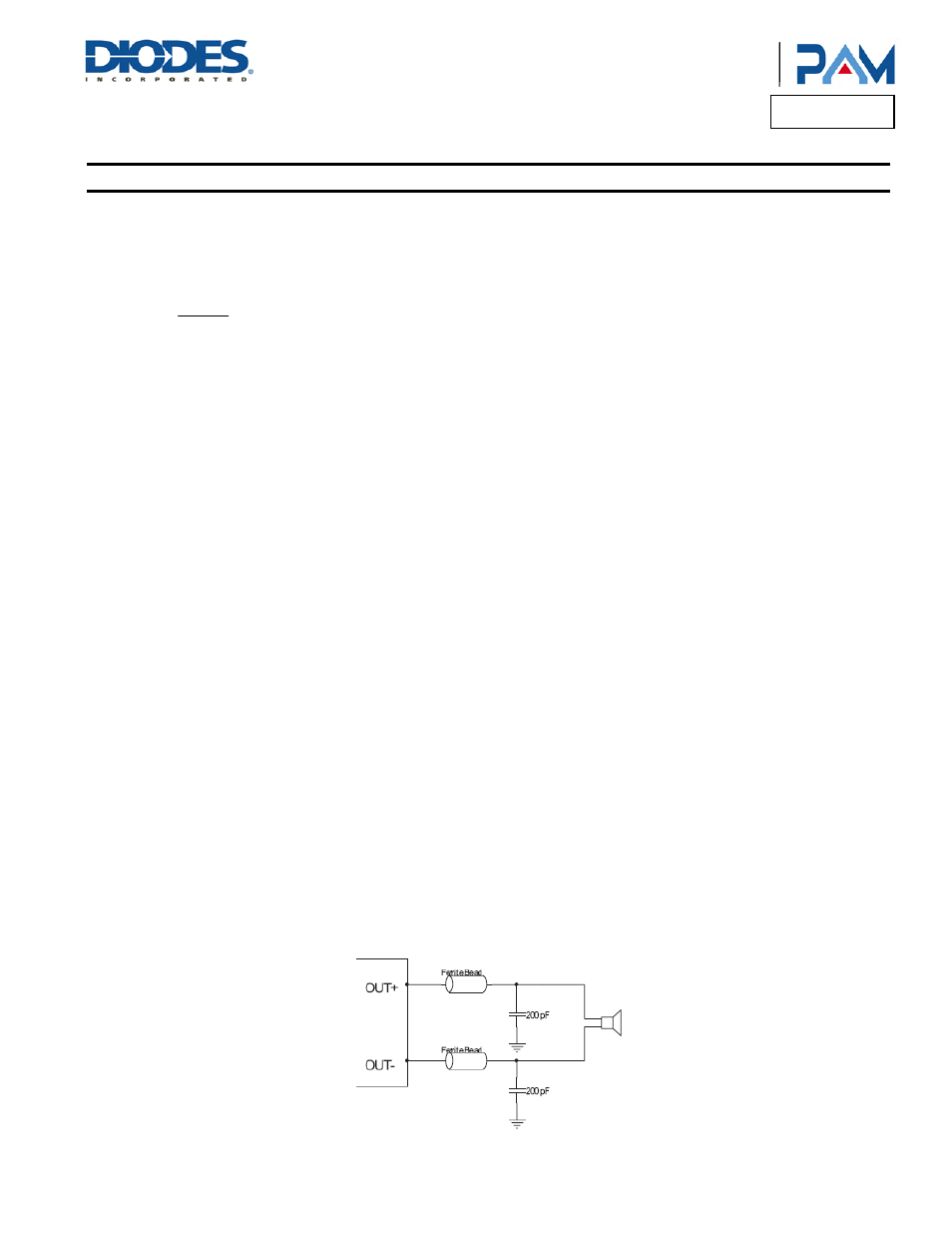
How to Reduce EMI (Electro Magnetic Interference)
A simple solution is to put an additional capacitor 1000µF at power supply terminal for power line coupling if the traces from amplifier to speakers
are short (< 20cm).
Most applications require a ferrite bead filter as shown at Figure 3. The ferrite filter reduces EMI of around 1 MHz and higher. When selecting a
ferrite bead, choose one with high impedance at high frequencies, and low impedance at low frequencies (MH2012HM221-T).
Figure 3. Ferrite Bead Folter to reduce EMI