Pam8615, Application information – Diodes PAM8615 User Manual
Page 11
PAM8615
Document number: DSxxxxx Rev. 1 - 1
11 of 14
www.diodes.com
October 2012
© Diodes Incorporated
PAM8615
A Product Line of
Diodes Incorporated
Application Information
(cont.)
Using low-ESR Capacitors
Low - ESR capacitors are recommended throughout this application section. A real (with respect to ideal) capacitor can be modeled simply as a
resistor in series with an ideal capacitor. The voltage drop across this resistor minimizes the beneficial effects of the capacitor in the circuit. The
lower the equivalent value of this resistance the more the real capacitor behaves as an ideal capacitor.
Short-Circuit Protection
The PAM8615 has short circuit protection circuitry on the outputs to prevent damage to the device when output-to-output shorts (BTL mode),
output-to- GND shorts, or output-to-VCC shorts occur. Once a short-circuit is detected on the outputs, the output drive is immediately disabled.
This is a latched fault and must be reset by cycling the voltage on the SD pin to a logic low and back to the logic high state for normal operation.
This will clear the short-circuit flag and allow for normal operation if the short was removed. If the short was not removed, the protection circuitry
will again activate.
Thermal Protection
Thermal protection on the PAM8615 prevents damage to the device when the internal die temperature exceeds +160°C. There is a ±15 degree
tolerance on this trip point from device to device. Once the die temperature exceeds the set thermal point, the device enters into the shutdown
state and the outputs are disabled. This is not a latched fault. The thermal fault is cleared once the temperature of the die is reduced by +40°C.
The device begins normal operation at this point without external system intervention.
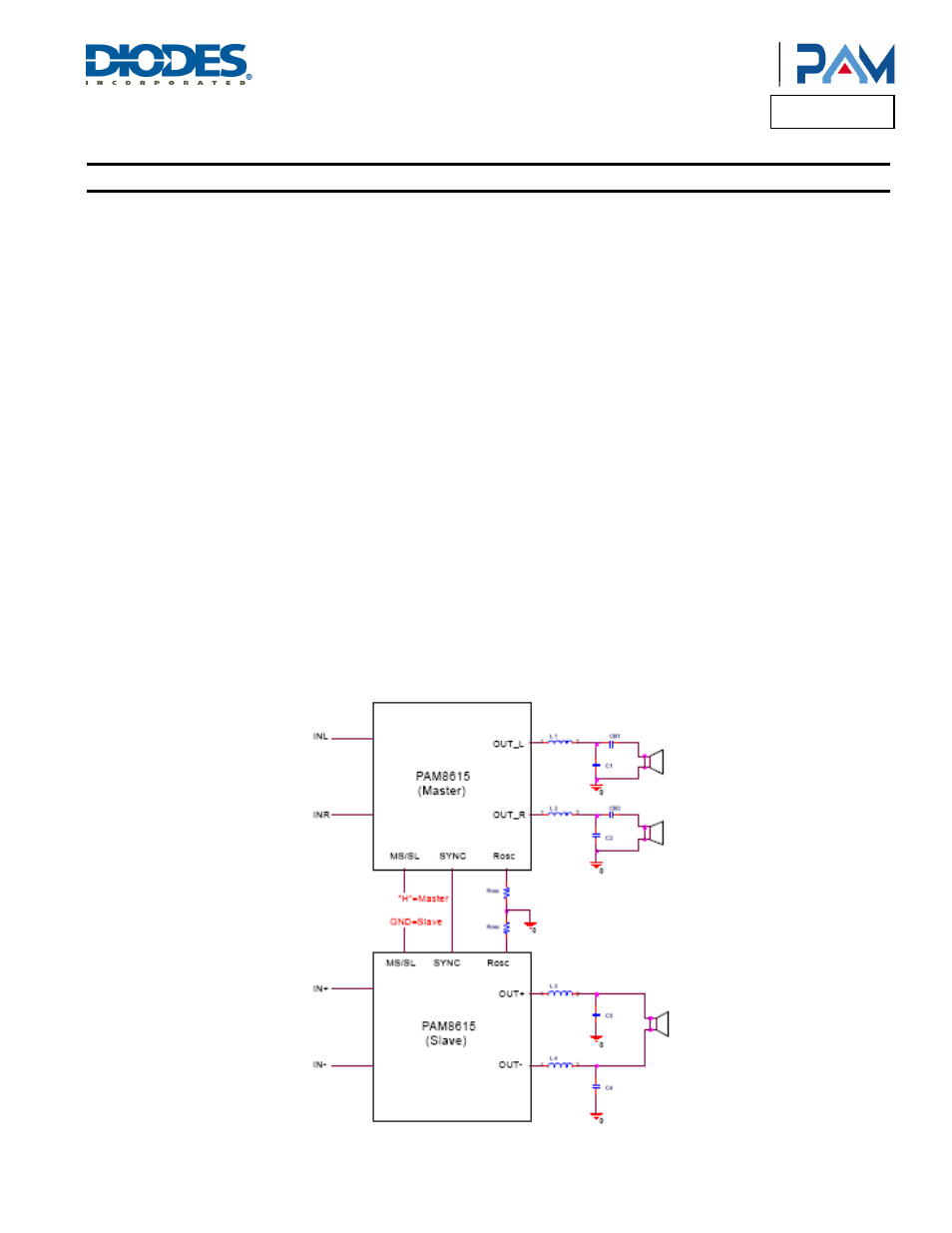
Master-Slave and SYNC Operation
The MS/SL and SYNC terminals can be used to synchronize the frequency of the class-D output switching. When the MS/SL is high or left
floating due to the internal pull up resistor, the switching frequency is determined by the ROSC. The SYNC becomes an output whose
source/sink current is about 0.5mA, and the frequency of this output is also determined by the ROSC. And this output can be connected to
another PAM8615 who is configured in the slave mode. The output switching is synchronized to avoid any beat frequencies that occur in the
audio band when two Class-D amplifiers in the same system are switching at the slight different frequencies. When the MS/SL is low, the
switching frequency is determined by the incoming square wave on the SYNC input. The SNYC becomes an input in this mode and accept a
square wave from another PAM8615 configured in the master mode or from an external GPIO.
(Key: MS/SL = ”H”, Master Mode, MS/SL = ”L”, Slave Mode)