Pam2842, Absolute maximum ratings, Recommended operating conditions – Diodes PAM2842 User Manual
Page 4: Thermal information, Electrical characteristics
PAM2842
Document number: DSxxxxx Rev. 1 - 2
4 of 17
www.diodes.com
October 2012
© Diodes Incorporated
PAM2842
A Product Line of
Diodes Incorporated
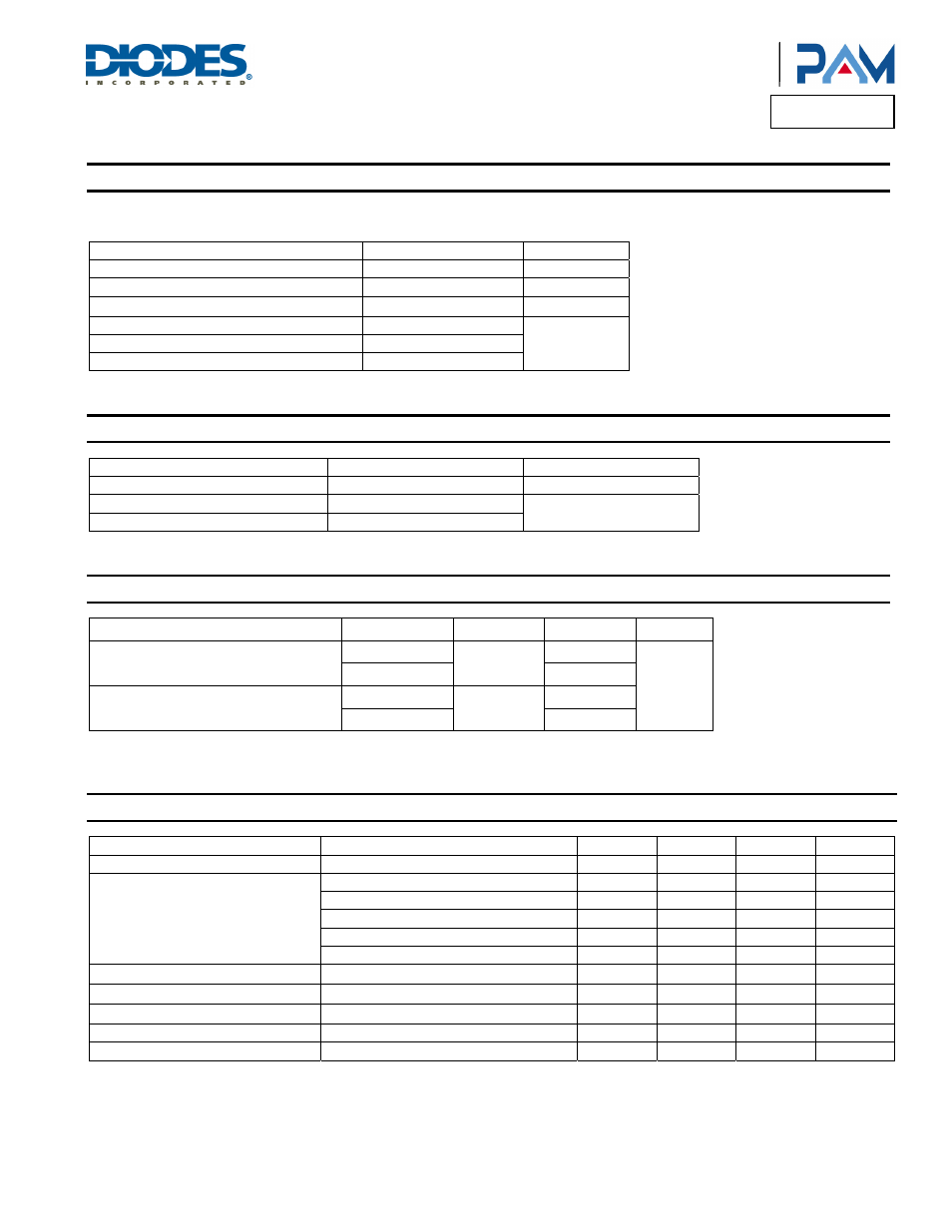
Absolute Maximum Ratings
(@T
A
= +25°C, unless otherwise specified.)
These are stress ratings only and functional operation is not implied. Exposure to absolute maximum ratings for prolonged time periods may
affect device reliability. All voltages are with respect to ground.
Parameter Rating
Unit
Supply Voltage
40
V
Buck Application Maximum Output Current
3
A
I/O Pin Voltage Range
GND -0.3 to V
DD
+0.3
V
Maximum Junction Temperature
150
°C
Storage Temperature
-40 to +150
Soldering Temperature
300, 5sec
Recommended Operating Conditions
(@T
A
= +25°C, unless otherwise specified.)
Parameter
Rating
Unit
Supply Voltage Range
5.5 to 40
V
Operation Temperature Range
-40 to +85
°C
Junction Temperature Range
-40 to +125
Thermal Information
Parameter Package
Symbol
Max
Unit
Thermal Resistance (Junction to Case)
TSSOP-20
θ
JC
20
°C/W
QFN6x6-40 7.6
(Note
1)
Thermal Resistance (Junction to Ambient)
TSSOP-20
θ
JA
90
QFN6x6-40
18.1 (Note 1)
Note:
1. The exposed PAD must be soldered to a thermal land on the PCB.
Electrical Characteristics
(@T
A
= +25°C, V
EN
= V
DD
= 24V, 1W x 10 LEDs, unless otherwise specified.)
Parameter Test
Conditions
Min
Typ
Max
Units
Input Voltage Range
5.5
40
V
Quiescent Current
E NA = high (no switching frequency)
1
2
mA
E NA = high (1M switching frequency)
6
mA
E NA = high (500k switching frequency)
3
mA
E NA = high (200k switching frequency)
1.6
mA
E NA = low
5
10
µA
Feedback Voltage, Low Side
V
FB
= V
SENSE+
-AGND, V
SENSE-
= AGND
95 100 105 mV
Feedback Voltage, High Side
V
FB
= V
SENSE+
– V
SENSE-
95 100 105 mV
LED Current Line Regulation
I
O
= 350mA
0.02 %/V
LED Current Load Regulation
1.0
%
VDD_DR UVLO Hysteresis
No Switching
200 mV