Pam2842, Application information – Diodes PAM2842 User Manual
Page 10
PAM2842
Document number: DSxxxxx Rev. 1 - 2
10 of 17
www.diodes.com
October 2012
© Diodes Incorporated
PAM2842
A Product Line of
Diodes Incorporated
Application Information
(cont.)
Diode Selection
PAM2842 is a high switching frequency converter which demands high speed rectifier. It's indispensable to use a Schottky diode rated at 3A,
40V with the PAM2842. Using a Schottky diode with a lower forward voltage drop is better to improve the power LED efficiency.
In boost topology, the voltage rating should be higher than V
OUT
and in buck topology, the voltage rating higher than V
IN
, the peak current is
2
I
I
I
L
L
)
MAX
(
D
Δ
+
=
in sepic topology, the voltage rating should be higher than V
IN
+V
OUT
, the peak current is
I
I
I
)
PEAK
(
2
L
)
PEAK
(
1
L
)
MAX
(
D
+
=
The average current of the diode equals to I
O
.
Work Frequency Selection
PAM2842 working frequency is decided by resistor connect to the RT pin, it can be calculated by follow equation:
)
Hz
(
)
K
12
RT
(
x
24
10
F
12
SW
+
=
From the equations, we can see when working frequency is high, the inductance can be small. It's important in some size limit application. But
we should know when the working frequency is higher, the switching loss is higher too. We must pay attention to thermal dissipation in this
application.
Methods for Setting LED Current
There are two methods for setting and adjusting the LED current:
1) R
SENSE
only
2) PWM signal with external components
a) Use the COMP pin
b) Use the Sense pin
●
Method 1: LED Current Setting with Resistor R
SENSE
The most basic means of setting the LED current is connecting a resistor between R
SENSE
+ and R
SENSE
-. The LED current is decided by ISET
Resistor R
SENSE
.
I
LED
= 0.1/ R
SENSE
For flowing the large current, must pay attention to power dissipation on the resistor.
R
SENSE
has two positions to select: high side current sense and low side current sense. In buck topology it just has high side current sense. In
other topology we recommend use low side current sense for easier PCB layout.
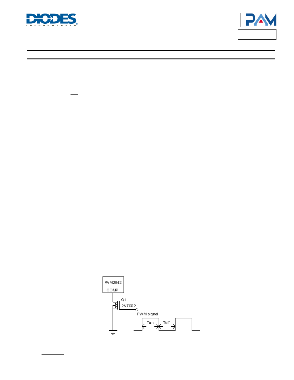
● Method 2: LED Current Setting with PWM Signal Using COMP Pin
This circuit uses resistor Rsense to set the on state current and the average LED current, then proportional to the percentage of off-time when
the COMP pin is logic high. Here use a invert component 2N7002 (Q1) to isolate and invert the PWM signal (See Figure 1).
Figure 1. PWM Dimming Use COMP Pin
Average LED current is approximately equal to:
T
T
I
T
I
OFF
ON
LED
OFF
AVG
+
=