Electrical characteristics, A product line of diodes incorporated – Diodes ZXTP25060BFH User Manual
Page 4
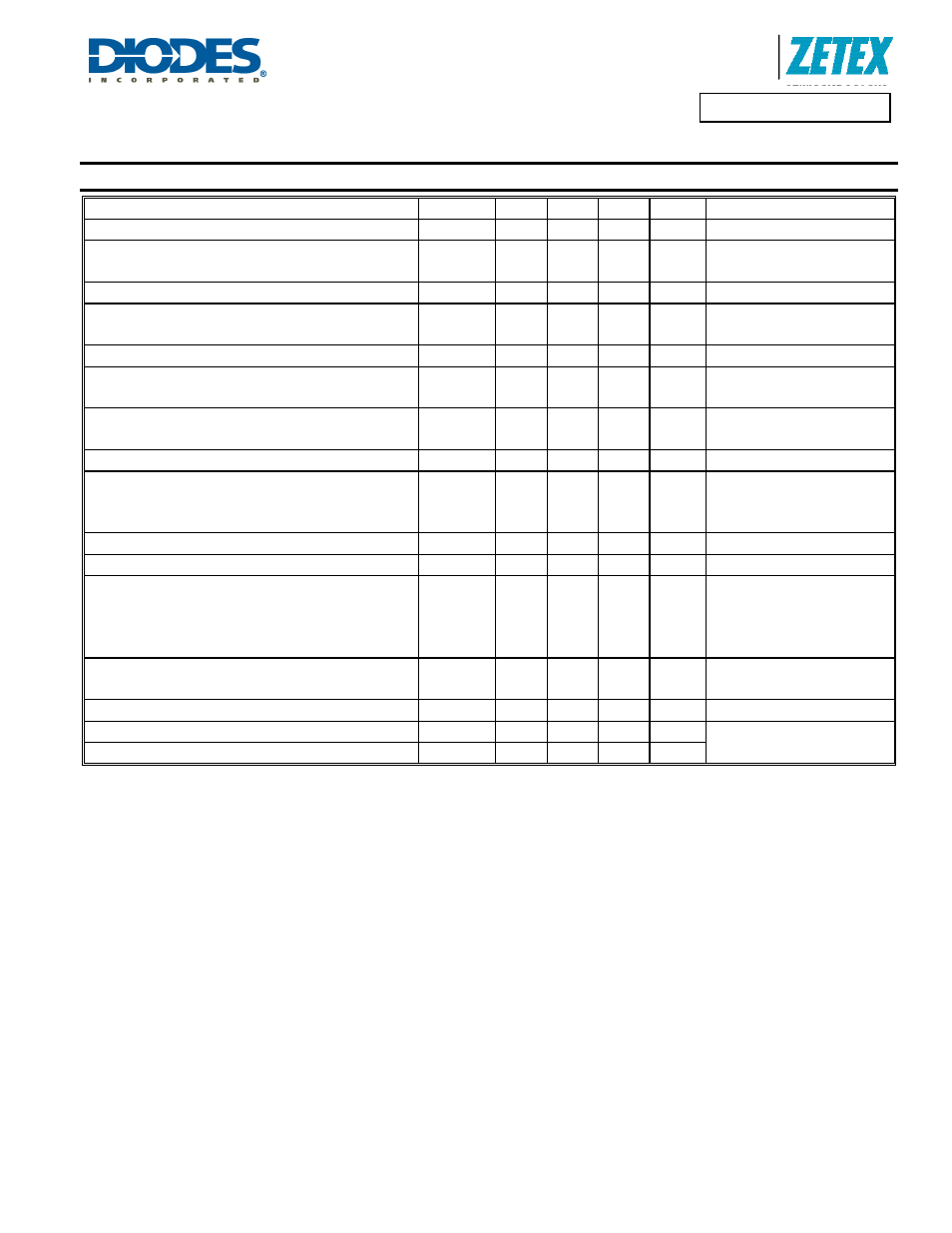
ZXTP25060BFH
Document number: DS33374 Rev. 4 - 2
4 of 7
January 2012
© Diodes Incorporated
A Product Line of
Diodes Incorporated
ZXTP25060BFH
Electrical Characteristics
@T
A
= 25°C unless otherwise specified
Characteristic Symbol
Min
Typ
Max
Unit
Test
Condition
Collector-Base Breakdown Voltage
BV
CBO
-100 -120 -
V I
C
= -100 µA
Collector-Emitter Breakdown Voltage (forward blocking)
BV
CEX
-100 -120 -
V
I
C
= -100 µA,
R
BE
< 1k
Ω or -0.25V < V
BE
< 1V
Collector-Emitter Breakdown Voltage (base open) (Note 9)
BV
CEO
-60 -80 -
V
I
C
= -10mA
Emitter- Collector Breakdown Voltage
(Reverse blocking) (Note 9)
BV
ECO
-7 -8.6 -
V
I
E
= -100µA
Emitter-Base Breakdown Voltage
BV
EBO
-7 -8.1 -
V
I
E
= -100µA
Collector Cutoff Current
I
CBO
-
-
< -1
-
-50
-20
nA
µA
V
CB
= -80V
V
CB
= -80V, T
A
= 100°C
Collector emitter Cutoff Current
I
CEX
- -
-100
nA
V
CE
= -80V,
R
BE
< 1k
Ω or -0.25V < V
BE
< 1V
Emitter Cutoff Current
I
EBO
- <
-1
-50 nA
V
EB
= -6V
Static Forward Current Transfer Ratio (Note 9)
h
FE
100
75
30
200
150
60
300
-
-
-
I
C
= -10mA, V
CE
= -2V
I
C
= -1A, V
CE
= -2V
I
C
= -3A, V
CE
= -2V
Base-Emitter Saturation Voltage (Note 9)
V
BE(sat)
- -940
-1040
mV
I
C
= -3A, I
B
= -300mA
Base-Emitter turn-on Voltage (Note 9)
V
BE(on)
- -830
-930 mV
I
C
= -3A, V
CE
= -2V
Collector-Emitter Saturation Voltage (Note 9)
V
CE(sat)
-
-
-
-
-45
-100
-70
-175
-55
-135
-85
-235
mV
I
C
= -0.5A, I
B
= -50mA
I
C
= -0.5A, I
B
= -10mA
I
C
= -1A, I
B
= -100mA
I
C
= -3A, I
B
= -300mA
Transition Frequency
f
T
- 250 - MHz
I
C
= -100mA, V
CE
= -5V,
f = 100MHz
Collector Output Capacitance (Note 9)
C
OBO
- 17.6 30 pF
V
CB
= -10V, f = 1MHz
Turn-on time
t
(on)
- 26.5 - ns
V
CC
= -10V, I
C
= -500mA,
I
B1
= I
B2
= -50mA
Turn-off time
t
(off)
- 291 - ns
Notes:
9. Measured under pulsed conditions. Pulse width
≤ 300
µs. Duty cycle
≤ 2%