Electrical characteristics, A product line of diodes incorporated – Diodes ZXTP26020DMF User Manual
Page 3
ZXTP26020DMF
Document number: DS32101 Rev. 1 - 2
3 of 6
May 2010
© Diodes Incorporated
A Product Line of
Diodes Incorporated
ZXTP26020DMF
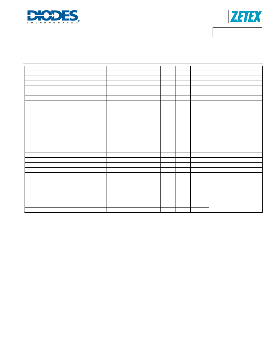
Electrical Characteristics
(at T
A
= 25°C unless otherwise specified)
Characteristic Symbol
Min
Typ
Max
Unit
Test
Condition
Collector-Base Breakdown Voltage
V
(BR)CBO
-20
⎯
⎯
V
I
C
= -100
μA, I
E
= 0A
Collector-Emitter Breakdown Voltage (Note 5)
V
(BR)CEO
-20
⎯
⎯
V
I
C
= -10mA, I
B
= 0A
Emitter-Base Breakdown Voltage
V
(BR)EBO
-7
⎯
⎯
V
I
E
= -100
μA, I
C
= 0A
Collector Cutoff Current
Icbo
⎯
⎯
-100
-0.5
nA
μA
V
CB
= -20V, I
E
= 0A
V
CB
= -20V, I
E
= 0A,T
A
= 125
°C
Emitter Cutoff Current
Ices
⎯
⎯
-100 nA
V
CE
= -20V, V
BE
= 0V
Base Cutoff Current
Iebo
⎯
⎯
-50
nA
V
BE
= -6V, I
C
= 0A
DC Current Gain (Note 5)
h
FE
300
235
175
140
⎯
⎯
⎯
⎯
⎯
⎯
⎯
⎯
⎯
V
CE
= -2V, I
C
= -100mA
V
CE
= -2V, I
C
= -0.5A
V
CE
= -2V, I
C
= -1A
V
CE
= -2V, I
C
= -1.5A
Collector-Emitter Saturation Voltage (Note 5)
V
CE(SAT)
⎯
⎯
⎯
⎯
⎯
⎯
⎯
⎯
-80
-100
-155
-235
mV
mV
mV
mV
I
C
= -100mA, I
B
= -1mA
I
C
= -500mA, I
B
= -50mA
I
C
= -1A, I
B
= -50mA
I
C
= -1.25A, I
B
= -62.5mA
Equivalent On-Resistance
R
CE(SAT)
⎯
125
⎯
m
Ω
I
C
= -1A, I
B
= -50mA
Base-Emitter Turn-On Voltage
V
BE(ON)
⎯
⎯
-1.1 V
V
CE
= -5V, I
C
= -1A
Base-Emitter Saturation Voltage
V
BE(SAT)
⎯
⎯
-1.15
V
I
C
= -1A, I
B
= -50mA
Output Capacitance (Note 5)
C
obo
⎯
⎯
20 pF
V
CB
= -10V, f = 1.0MHz
Current Gain-Bandwidth Product
f
T
200
⎯
⎯
MHz
V
CE
= -10V, I
C
= -50mA,
f = 100MHz
Turn-On Time
t
on
⎯
60
⎯
ns
V
CC
= -10V, I
C
= -1A
I
B2
= -I
B1
= -50mA
Delay Time
t
d
⎯
20
⎯
ns
Rise Time
t
r
⎯
40
⎯
ns
Turn-Off Time
t
off
⎯
167
⎯
ns
Storage Time
t
s
⎯
140
⎯
ns
Fall Time
t
f
⎯
27
⎯
ns
Notes:
5. Short duration pulse test used to minimize self-heating effect.