Diodes DMC4050SSD User Manual
Dmc4050ssd, Product summary, Description and applications
DMC4050SSD
Document number: DS33310 Rev. 2 - 2
1 of 11
March 2011
© Diodes Incorporated
DMC4050SSD
A Product Line of
Diodes Incorporated
40V COMPLEMENTARY PAIR ENHANCEMENT MODE MOSFET
Product Summary
Device
V
(BR)DSS
R
DS(on)
max
I
D
max
T
A
= 25
°C
(Notes 3 & 5)
Q1 40V
45m
Ω @ V
GS
= 10V
5.5A
60m
Ω @ V
GS
= 4.5V
4.2A
Q2 -40V
45m
Ω @ V
GS
= -10V
-5.8A
60m
Ω @ V
GS
= -4.5V
-4.2A
Description and Applications
This MOSFET has been designed to ensure that R
DS(on)
of N and P
channel FET are matched to minimize losses in both arms of the
bridge. The DMC4040SSD is optimized for use in 3 phases brushless
DC motor circuits (BLDC), CCFL backlighting.
•
3 phases BLDC motor
•
CCFL backlighting
Features and Benefits
•
Matched N & P R
DS(on)
-
Minimizes power losses
•
Fast switching – Minimizes switching losses
•
Dual device – Reduces PCB area
•
"Green" component and RoHS compliant (Note 1)
•
Qualified to AEC-Q101 Standards for High Reliability
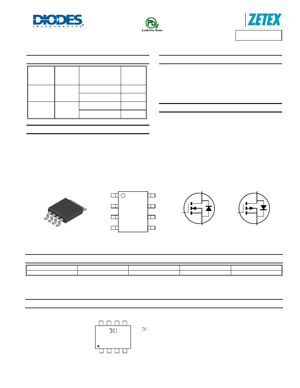
Mechanical Data
• Case:
SO-8
•
Case Material: Molded Plastic, “Green” Molding Compound. UL
Flammability Classification Rating 94V-0 (Note 1)
•
Moisture Sensitivity: Level 1 per J-STD-020
•
Terminals: Finish - Matte Tin annealed over Copper lead frame.
Solderable per MIL-STD-202, Method 208
•
Weight: 0.074 grams (approximate)
Ordering Information
(Note 1)
Product
Marking
Reel size (inches)
Tape width (mm)
Quantity per reel
DMC4050SSD-13 C4050SD
13
12
2,500
Notes:
1. Diodes, Inc. defines “Green” products as those which are RoHS compliant and contain no halogens or antimony compounds; further information about
Diodes Inc.’s “Green” Policy can be found on our website. For packaging details, go to our website.
Marking Information
SO-8
Top View
Top View
Equivalent Circuit
D1
S1
G1
S2
G2
D1
D2
D2
D1
S1
G1
D2
S2
G2
C4050SD
YY WW
= Manufacturer’s Marking
C4050SD = Product Type Marking Code
YYWW = Date Code Marking
YY = Year (ex: 10 = 2010)
WW = Week (01 - 53)