Maximum ratings (per leg), Thermal characteristics (per leg), Electrical characteristics (per leg) – Diodes MBRF20100CT User Manual
Page 2
MBR20100CT / MBRF20100CT
Document number: DS36343 Rev. 8 - 2
2 of 4
November 2013
© Diodes Incorporated
MBR20100CT / MBRF20100CT
ADVANCED INFORMATION
Maximum Ratings (Per Leg)
(@T
A
= +25°C, unless otherwise specified.)
Single phase, half wave, 60Hz, resistive or inductive load.
For capacitance load, derate current by 20%.
Characteristic Symbol
Value
Unit
Peak Repetitive Reverse Voltage
Working Peak Reverse Voltage
DC Blocking Voltage
V
RRM
V
RWM
V
RM
100 V
Average Rectified Output Current (Per Leg)
(Total)
I
O
10
20
A
Non-Repetitive Peak Forward Surge Current 8.3ms
Single Half Sine-Wave Superimposed on Rated Load
I
FSM
150 A
Thermal Characteristics (Per Leg)
Characteristic Symbol
Value
Unit
Typical Thermal Resistance, Junction to Case (Note 5)
Package = TO-220AB
Package = ITO-220AB
R
θJC
2
5
°C/W
Typical Thermal Resistance, Junction to Ambient (Note 5)
Package = TO-220AB
Package = ITO-220AB
R
θJA
13
20
°C/W
Operating and Storage Temperature Range
T
J
, T
STG
-55 to +175
°C
Electrical Characteristics (Per Leg)
(@T
A
= +25°C, unless otherwise specified.)
Characteristic Symbol
Min
Typ
Max
Unit
Test
Condition
Forward Voltage Drop
V
F
—
—
0.8
—
0.84
0.72
V
I
F
= 10A, T
A
= +25°C
I
F
= 10A, T
A
= +125°C
Leakage Current (Note 6)
I
R
—
—
—
—
0.05
10
mA
V
R
= 100V, T
A
= +25°C
V
R
= 100V, T
A
= +125°C
Notes:
5. Device mounted on Device with additional heat sink (45mm X 20mm X 12mm), with minimum recommended pad layout per6. Short duration pulse test used to minimize self-heating effect
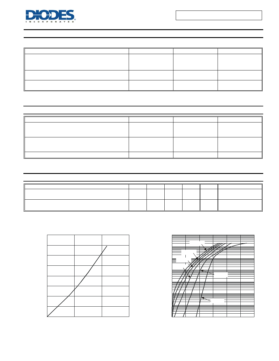
I
AVERAGE FORWARD CURRENT (A)
Figure 1 Forward Power Dissipation
F(AV)
P
,
P
O
WE
R
DIS
S
IP
A
T
IO
N (
W
)
D
0
1
2
3
4
5
6
7
8
0
5
10
15
V , INSTANTANEOUS FORWARD VOLTAGE (V)
F
Figure 2 Typical Forward Characteristics
I,
IN
S
TA
N
TA
N
E
O
U
S F
O
R
WA
R
D
C
U
R
R
E
N
T
(A
)
F
100
0
0.2
0.4
0.6
0.8
1
1.2
10
1
0.1
0.01
0.001
0.0001
T = -55°C
A
T = 25°C
A
T = 85°C
A
T = 125°C
A
T = 150°C
A
0.00001
T = 175°C
A