Diodes 74LVCE1G08 User Manual
Page 6
74LVCE1G08
SINGLE 2 INPUT POSITIVE AND GATE
74LVCE1G08
Document number: DS32213 Rev. 2 - 2
6 of 14
December 2010
© Diodes Incorporated
NEW PROD
UC
T
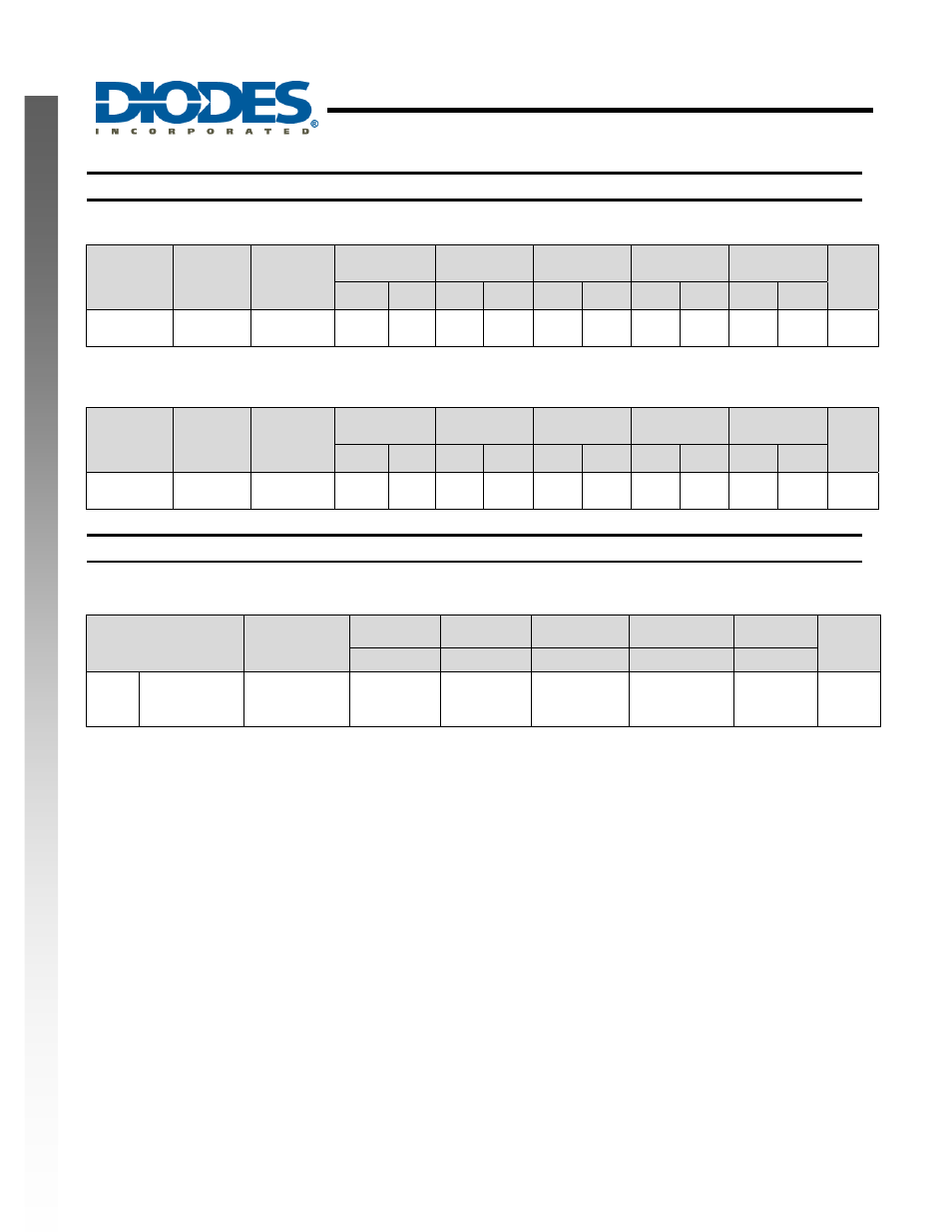
Switching Characteristics
Over recommended free-air temperature range, CL = 15pF (see Figure 1)
Parameter
From
(Input)
TO
(OUTPUT)
Vcc = 1.5 V
± 0.1V
Vcc = 1.8 V
± 0.15V
Vcc = 2.5 V
± 0.2V
Vcc = 3.3 V
± 0.3V
Vcc = 5 V
± 0.5V
Unit
Min
Max
Min
Max
Min
Max
Min
Max
Min
Max
t
pd
A or B
Y
1.5
7.2
1.0
5
0.5 3.5 0.6 2.9 0.7 2.9 ns
Over recommended free-air temperature range, CL = 30 or 50pF as noted (see Figure 2)
Parameter
From
(Input)
TO
(OUTPUT)
Vcc = 1.5 V
± 0.1V
Vcc = 1.8 V
± 0.15V
Vcc = 2.5 V
± 0.2V
Vcc = 3.3 V
± 0.3V
Vcc = 5 V
± 0.5V
Unit
Min
Max
Min
Max
Min
Max
Min
Max
Min
Max
t
pd
A or B
Y
2.4
8
1.6
5.6
0.8 4.4 0.8 3.6 0.9 3.6 ns
Operating Characteristics
T
A
= 25 ºC
Parameter
Test
Conditions
Vcc = 1.5 V Vcc = 1.8 V Vcc = 2.5 V
Vcc = 3.3 V
Vcc = 5 V
Unit
TYP
TYP
TYP
TYP
TYP
C
pd
Power
dissipation
capacitance
f = 10 MHz
21
21
24
26
31
pF