Single buffer gate with 3-state output, New prod uc t parameter measurement information – Diodes 74AHC1G125 User Manual
Page 6
74AHC1G125
SINGLE BUFFER GATE WITH 3-STATE OUTPUT
74AHC1G125
Document number: DS35176 Rev. 1 - 2
6 of 9
March 2011
© Diodes Incorporated
NEW PROD
UC
T
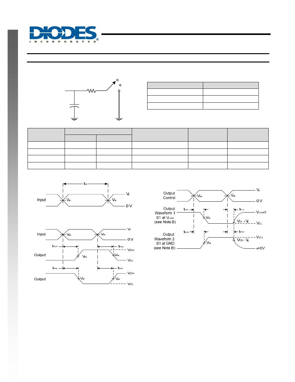
Parameter Measurement Information
R
L
C
L
(see Note A)
Under Test
Vcc
Open
GND
S1
=1 kΩ
TEST
S1
t
PLH
/t
PHL
Open
t
PLZ
/t
PZL
Vload
t
PHZ
/t
PZH
GND
V
CC
Inputs
V
M
C
L
V
∆
V
I
t
r
/t
f
3.3V±0.3V
V
CC
≤3ns
V
CC
/2
15pF 0.3V
5V±0.5V
V
CC
≤3ns
V
CC
/2
15pF 0.3V
3.3V±0.3V
V
CC
≤3ns
V
CC
/2
50pF 0.3V
5V±0.5V
V
CC
≤3ns
V
CC
/2
50pF 0.3V
Voltage Waveform Pulse Duration
Voltage Waveform Enable and Disable Times
Low and High Level Enabling
Voltage Waveform Propagation Delay Times
Inverting and Non Inverting Outputs
Figure 1. Load Circuit and Voltage Waveforms
Notes: A. Includes test lead and test apparatus capacitance.
B. All pulses are supplied at pulse repetition rate
≤ 1 MHz.
C. Inputs are measured separately one transition per measurement.
D. t
PLZ
and t
PHZ
are the same as t
dis
.
E. t
PZL
and t
PZH
are the same as t
EN
.
F. t
PLH
and t
PHL
are the same as t
PD
.