Parameter measuement information – Diodes 74LVC126A User Manual
Page 6
74LVC126A
Document number: DS35266 Rev. 3 - 2
6 of 10
June 2012
© Diodes Incorporated
74LVC126A
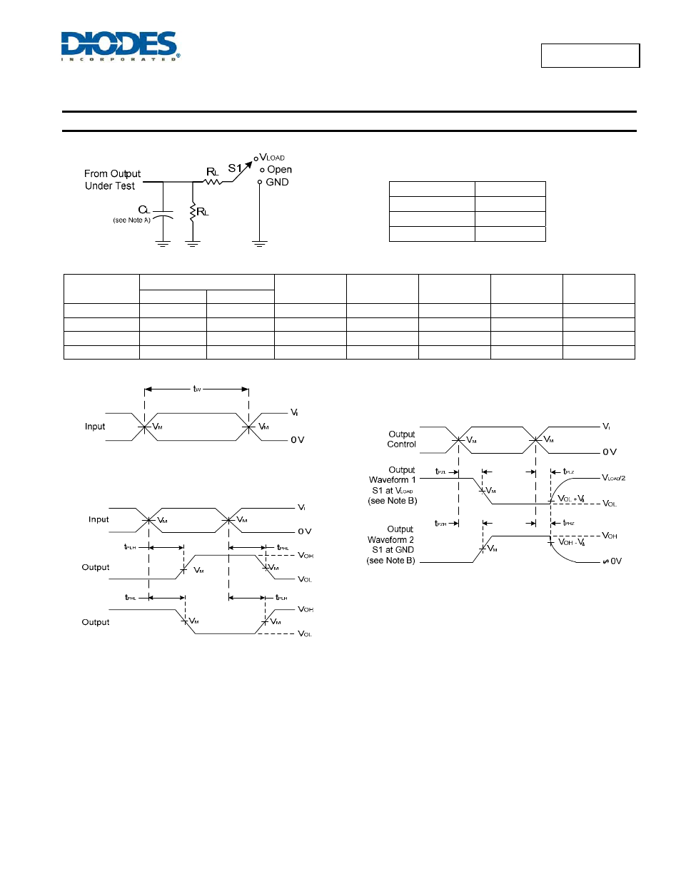
Parameter Measuement Information
V
CC
Inputs
V
M
V
LOAD
C
L
R
L
V
∆
V
I
t
r
/t
f
1.8V±0.15V
V
CC
≤2ns
V
CC
/2
2 x V
CC
30pF 1K
Ω 0.15V
2.5V±0.2V
V
CC
≤2ns
V
CC
/2
2 x V
CC
30pF 500
Ω 0.15V
2.7V 2.7V
≤2.5ns 1.5V
6V
50pF 500
Ω 0.3V
3.3V±0.3V 2.7V
≤2.5ns 1.5V
6V
50pF 500
Ω 0.3V
Voltage Waveform Enable and Disable Times
Low and High Level Enabling
Voltage Waveform Pulse Duration
Voltage Waveform Propagation Delay Times
Inverting and Non Inverting Outputs
Notes: A. Includes test lead and test apparatus capacitance.
B. All pulses are supplied at pulse repetition rate
≤ 10 MHz.
C. Inputs are measured separately one transition per measurement.
D. t
PLZ
and t
PHZ
are the same as t
dis.
E. t
PZL
and t
PZH
are the same as t
EN0
F. t
PLH
and t
PHL
are the same as t
PD.
Figure 1. Load Circuit and Voltage Waveforms
TEST S1
t
PLH
/t
PHL
Open
t
PLZ
/t
PZL
VLOAD
t
PHZ
/t
PZH
GND
- PDS3200 (5 pages)
- PDS340 (5 pages)
- PDS340Q (5 pages)
- PDS360 (5 pages)
- PDS360Q (5 pages)
- PDS4150 (4 pages)
- PDS3100Q (5 pages)
- PDS3100 (5 pages)
- PDS1240CTL (5 pages)
- PDS1045 (5 pages)
- PDS1040L (5 pages)
- PDS1040CTL (5 pages)
- PDS1040 (5 pages)
- PD3S230L (5 pages)
- PD3S230H (3 pages)
- PDS5100Q (5 pages)
- PDS835L (5 pages)
- PDS760 (5 pages)
- PDS560 (5 pages)
- PDS540 (5 pages)
- PDS5100H (5 pages)
- PDS5100 (5 pages)
- PDS4200H (6 pages)
- SBL3060CTP (4 pages)
- SBL30L30CT (3 pages)
- SBL3045CTP (4 pages)
- SBL3040CTP (4 pages)
- SBL2060CTP (4 pages)
- SBL2030CT - SBL2060CT (3 pages)
- SBL2045CTP (4 pages)
- SBL1060CTP (4 pages)
- SBL1040CTP (4 pages)
- SBG3030CT - SBG3045CT (5 pages)
- SB520 - SB560 (3 pages)
- SB370 - SB3100 (3 pages)
- SB320 - SB360 (3 pages)
- SBR10U100CT (5 pages)
- SBR10U150CT (5 pages)
- SBR10A45SP5 (5 pages)
- SBR1060CT (5 pages)
- SBR1045SP5 (5 pages)
- SBR1045SD1 (4 pages)
- SBR1045D1 (5 pages)
- SBR1045CTL (4 pages)
- SBR1040CT (5 pages)