Recommended operating conditions, Electrical characteristics, Operating characteristics – Diodes 74HC594 User Manual
Page 4
74AHC594
Document number: DS35484 Rev. 3 - 2
4 of 10
June 2013
© Diodes Incorporated
74HC594
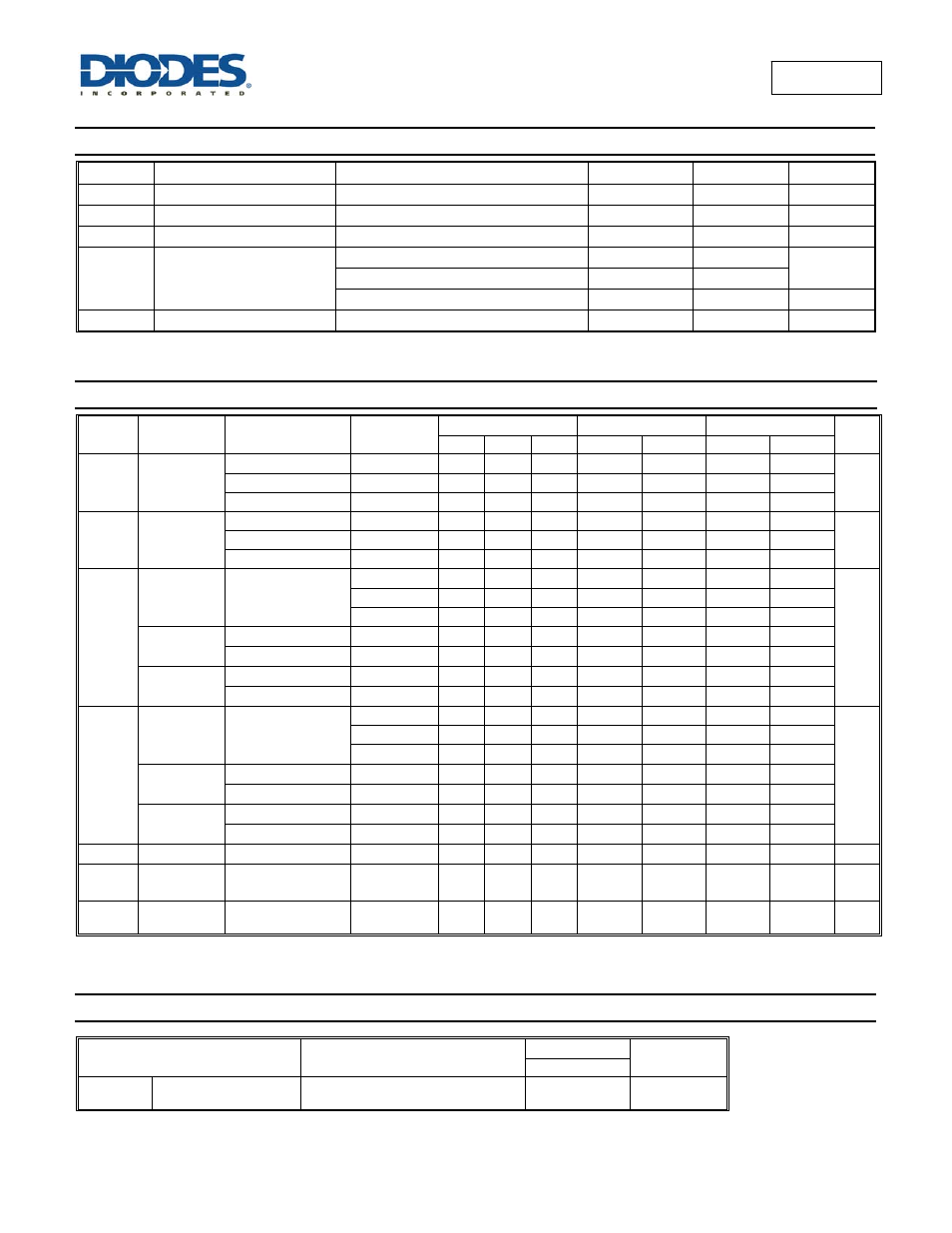
Recommended Operating Conditions
(Note 5) (@T
A
= +25°C, unless otherwise specified.)
Symbol Parameter
Conditions
Min Max
Unit
V
CC
Supply Voltage
2.0 6.0 V
V
I
Input Voltage
0 Vcc
V
V
O
Output Voltage
0
V
CC
V
Δt/ΔV
Input transition rise or fall rate
V
CC
= 2.0V
1000
ns/V
V
CC
= 4.5V
500
V
CC
= 6.0V
400
T
A
Operating free-air temperature
-40 +125
°C
Note:
5. Unused inputs should be held at V
CC
or Ground.
Electrical Characteristics
(@T
A
= +25°C, unless otherwise specified.)
Symbol Parameter Test
Conditions
V
CC
T
A
= +25°C
T
A
= -40°C to +85°C T
A
= -40°C to +125°C
Unit
Min
Typ
Max
Min Max Min Max
V
IH
High-level
Input Voltage
2.0V
1.5 1.2
1.5
1.5
V
4.5V
3.15 2.4
3.15
3.15
6.0V
4.2 3.2
4.2
4.2
V
IL
Low-level
input voltage
2.0V
0.8 0.5
0.5
0.5
V
4.5V
2.1 1.35
1.35
1.35
6.0V
2.8 1.8
1.8
1.8
V
OH
High Level
Output
Voltage
I
OH
= -20μA
All outputs
2.0V
1.9 2.0
1.9
1.9
V
4.5V
4.4 4.5
4.4
4.4
6.0V
5.9 6.0
5.9
5.9
Q7S output
I
OH
= -4mA
4.5V
3.98 4.32
3.84
3.7
I
OH
= -5.2mA
6.0V
5.48 5.81
5.34
5.2
Qn Bus
Outputs
I
OH
= -6.0mA
4.5V
3.98 4.32
3.84
3.7
I
OH
= -7.8mA
6.0V
5.48 5.81
5.34
5.2
V
OL
Low-level
Output
Voltage
I
OL
= 20μA
All outputs
2.0V
0 0.1
0.1
0.1
V
4.5V
0 0.1
0.1
0.1
6.0V
0 0.1
0.1
0.1
Q7S output
I
OL
= 4.0mA
4.5V
.15 0.26
0.33
0.4
I
OL
= 5.2mA
6.0V
.16 0.26
0.33
0.4
Qn Bus
Outputs
I
OL
= 6.0mA
4.5V
.15 0.26
0.33
0.4
I
OL
= 7.8mA
6.0V
.16 0.26
0.33
0.4
I
I
Input Current V
I
= GND to 5.5V
6.0V
±0.1
± 1
± 1
μA
I
CC
Supply
Current
V
I
= GND or V
CC
I
O
= 0
6.0V
8.0
80
160
μA
C
i
Input
Capacitance V
i
= V
CC
– or GND
6.0V
3.5 10
10
10 pF
Operating Characteristics
(@T
A
= +25°C, unless otherwise specified.)
Parameter
Test
Conditions
V
CC
= 5V
Unit
Typ
C
pd
Power dissipation
capacitance
f = 1 MHz all outputs switching-no load
51 pF