Diodes 74HC125 User Manual
Description, Features, Pin assignments
74HC125
Document number: DS35326 Rev. 3 - 2
1 of 9
January 2013
© Diodes Incorporated
74HC125
QUADRUPLE 3-STATE BUFFERS OE LOW
Description
The 74HC125 provides provides four independent buffer gates with
3-state outputs. Each buffer has a separate enable pin that if driven
with a high logic level places the corresponding output in the high
impedance state. The device is designed for operation with a power
supply range of 2.0V to 6.0V.
Features
•
Wide Supply Voltage Range from 2.0V to 6.0V
•
Sinks or sources 4mA at V
CC
= 4.5V
•
CMOS low power consumption
•
Schmitt Trigger Action at All Inputs
•
ESD Protection Exceeds JESD 22
200-V Machine Model (A115-A)
2000-V Human Body Model (A114-A)
Exceeds 1000-V Charged Device Model (C101C)
•
Range of Package Options SO-14 and TSSOP-14
•
Totally Lead-Free & Fully RoHS Compliant (Notes 1 & 2)
•
Halogen and Antimony Free. “Green” Device (Note 3)
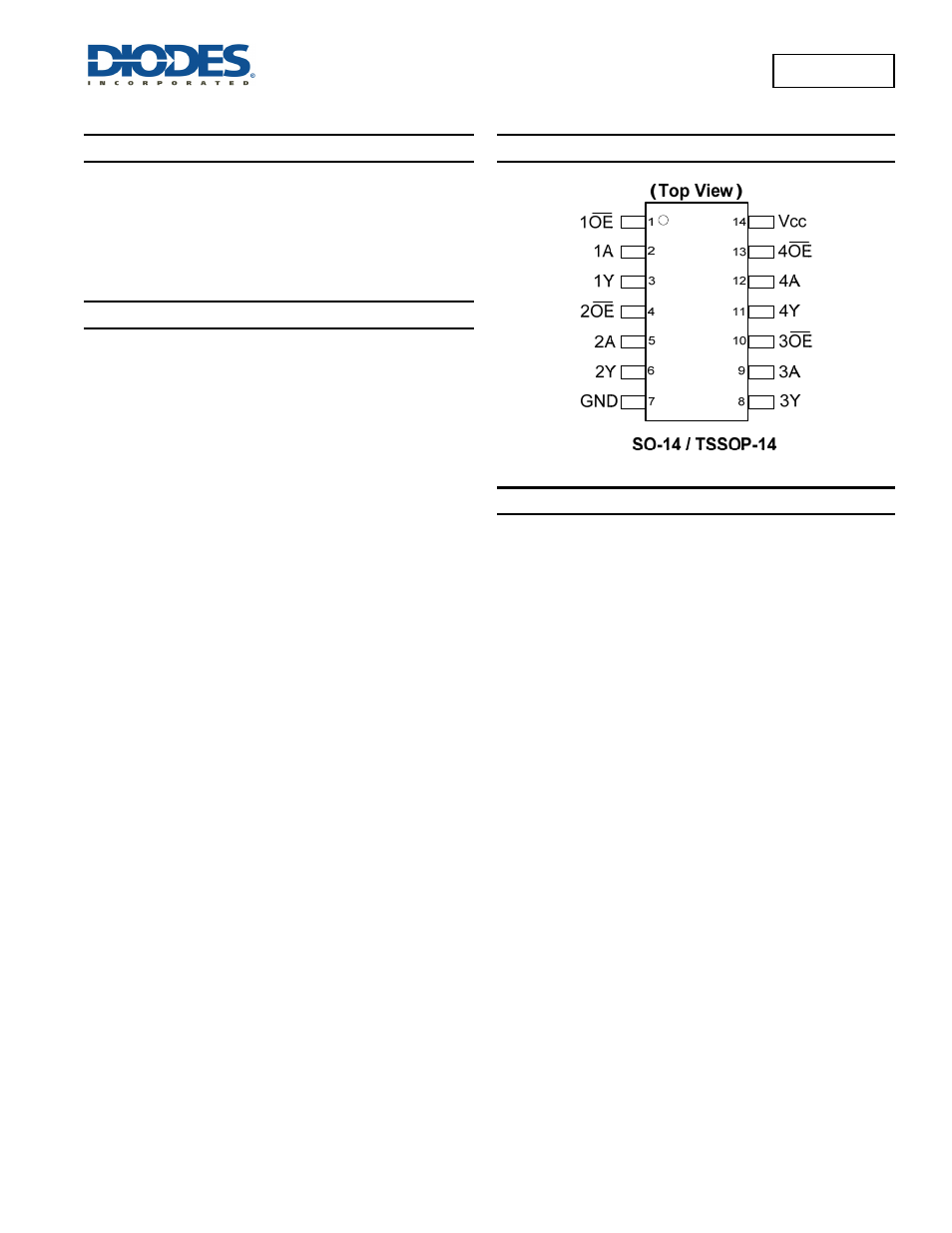
Pin Assignments
Applications
• General Purpose Logic
• Wide array of products such as:
PCs, Networking, Notebooks, Netbooks
Computer Peripherals, Hard Drives, CD/DVD ROM
TV, DVD, DVR, Set Top Box
Notes:
1. No purposely added lead. Fully EU Directive 2002/95/EC (RoHS) & 2011/65/EU (RoHS 2) compliant.
2. Se information about Diodes Incorporated’s definitions of Halogen- and Antimony-free, "Green" and Lead-free.
3. Halogen- and Antimony-free "Green” products are defined as those which contain <900ppm bromine, <900ppm chlorine (<1500ppm total Br + Cl) and
<1000ppm antimony compounds.