Absolute maximum ratings, Recommended operating conditions – Diodes 74AUP2G3404 User Manual
Page 3
74AUP2G3404
Document number: DS36096 Rev. 4 - 2
3 of 12
December 2013
© Diodes Incorporated
NEW PROD
UC
T
74AUP2G3404
ADVANCED INFORMATION
ADVANCED INFORMATION
NEW PROD
UC
T
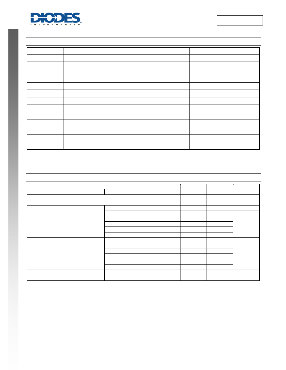
Absolute Maximum Ratings
(Note 4) (@T
A
= +25°C, unless otherwise specified.)
Symbol
Description Rating
Unit
ESD HBM
Human Body Model ESD Protection
2
KV
ESD CDM
Charged Device Model ESD Protection
1
KV
ESD MM
Machine Model ESD Protection
200
V
V
CC
Supply Voltage Range
-0.5 to 4.6
V
V
I
Input Voltage Range
-0.5 to 4.6
V
V
O
Voltage applied to output in high or low state
-0.5 to V
CC
+0.5
V
I
IK
Input Clamp Current V
I
< 0
50
mA
I
OK
Output Clamp Current (V
O
< 0 )
-50 mA
I
O
Continuous Output Current (V
O
= 0 to V
CC
)
±20 mA
I
CC
Continuous Current Through V
CC
50
mA
I
GND
Continuous Current Through GND
-50
mA
T
J
Operating Junction Temperature
-40 to +150
°C
T
STG
Storage Temperature
-65 to +150
°C
Note:
4. Stresses beyond the absolute maximum may result in immediate failure or reduced reliability. These are stress values and device
operation should be within recommend values.
Recommended Operating Conditions
(Note 5)
(@T
A
= +25°C, unless otherwise specified.)
Symbol
Parameter
Min
Max
Unit
V
CC
Operating Voltage
—
0.8
3.6
V
V
I
Input Voltage
0
3.6
V
V
O
Output Voltage
0
V
CC
V
I
OH
High-Level Output Current
V
CC
= 0.8V
— -20 µA
V
CC
= 1.1V
— -1.1
mA
V
CC
= 1.4V
— -1.7
V
CC
= 1.65V
— -1.9
V
CC
= 2.3V
— -3.1
V
CC
= 3.0V
— -4
I
OL
Low-Level Output Current
V
CC
= 0.8V
—
20 μA
V
CC
= 1.1V
—
1.1
mA
V
CC
= 1.4V
—
1.7
V
CC
= 1.65V
—
1.9
V
CC
= 2.3V
—
3.1
V
CC
= 3.0V
—
4
∆t/∆V
Input transition rise or fall rate
V
CC
= 0.8V to 3.6V
— 200 ns/V
T
A
Operating free-air temperature —
-40
+125
°C
Note: 5. Unused inputs should be held at V
CC
or Ground.