Operating characteristics, Parameter measurement information – Diodes 74AUP2G06 User Manual
Page 6
74AUP2G06
Document number: DS35510 Rev. 2 - 2
6 of 11
December 2013
© Diodes Incorporated
74AUP2G06
NEW PROD
UC
T
Operating Characteristics
(@T
A
= +25°C, unless otherwise specified.)
Parameter
Test
Conditions
V
CC
Typ Unit
C
pd
Power Dissipation Capacitance
f = 1MHz
No Load
0.8V 0.3
pF
1.2V ± 0.1V
0.4
1.5V ± 0.1V
0.5
1.8V ± 0.15V
0.5
2.5V ± 0.2V
0.5
3.3V ± 0.3V
0.6
C
I
Input Capacitance
V
I
= V
CC
or GND
0V or 3.3V
2.0
pF
C
O
Output Capacitance
V
O
= V
CC
or GND
0V
2.0
pF
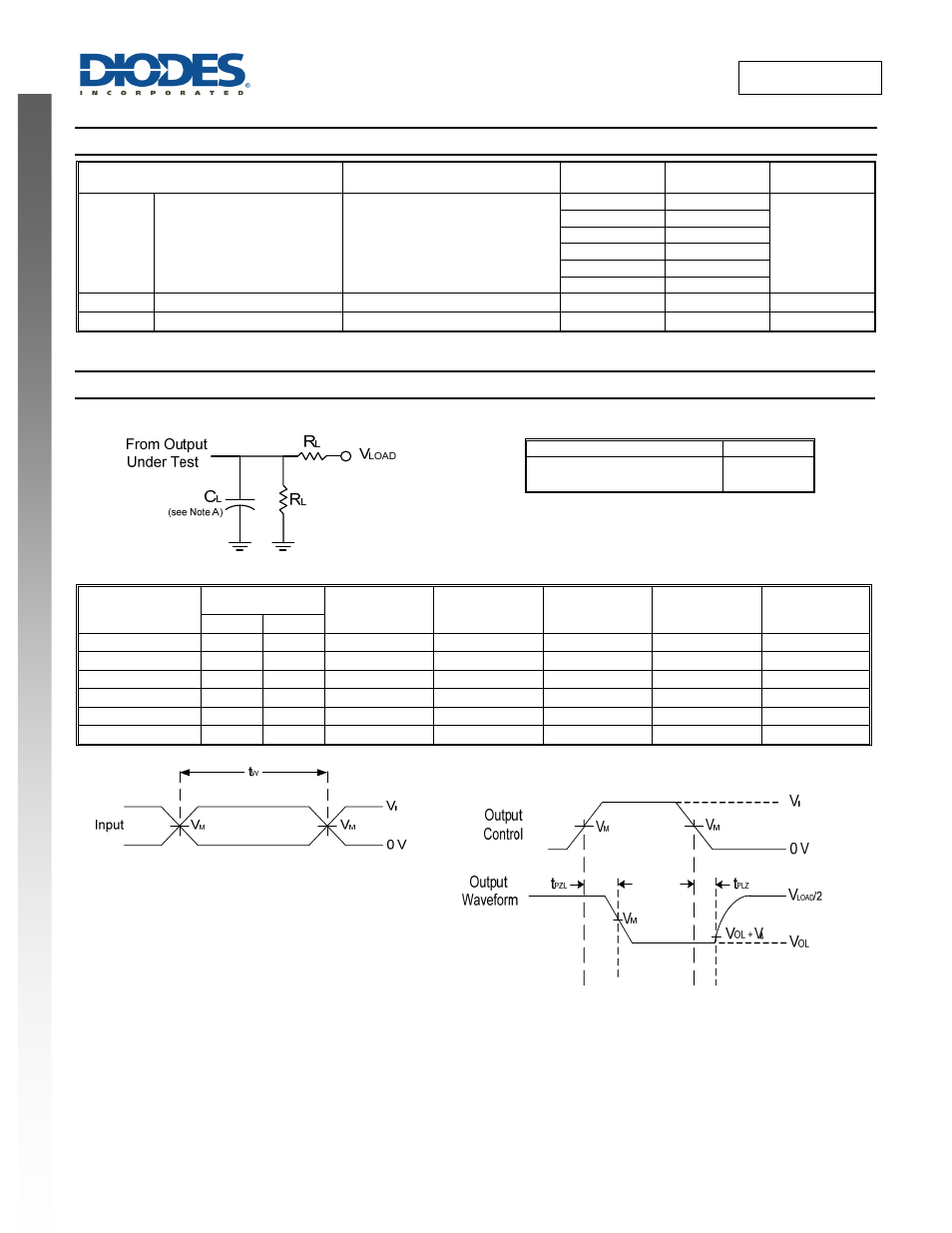
Parameter Measurement Information
TEST
Condition
t
PLZ
(see Notes D and E)
t
PZL
(see Notes D and F)
Vload
Vload
V
CC
Inputs
V
M
V
LOAD
C
L
R
L
V∆
V
I
t
r
/t
f
0.8V
V
CC
≤3 ns
V
CC
/2
2 X V
CC
5, 10, 15, 30pF
5kΩ 0.1V
1.2V±0.1V
V
CC
≤3 ns
V
CC
/2
2 X V
CC
5, 10, 15, 30pF
5kΩ 0.1V
1.5V±0.1V
V
CC
≤3 ns
V
CC
/2
2 X V
CC
5, 10, 15, 30pF
5kΩ 0.15V
1.8V±0.15V
V
CC
≤3 ns
V
CC
/2
2 X V
CC
5, 10, 15, 30pF
5kΩ 0.15V
2.5V±0.2V
V
CC
≤3 ns
V
CC
/2
2 X V
CC
5, 10, 15, 30pF
5kΩ 0.15V
3.3V±0.3V
V
CC
≤3 ns
V
CC
/2
2 X V
CC
5, 10, 15, 30pF
5kΩ 0.3V
Voltage Waveform Pulse Duration
Voltage Waveform Propagation Delay Times
Figure 1. Load Circuit and Voltage Waveforms
Notes: A. Includes test lead and test apparatus capacitance.
B. All pulses are supplied at pulse repetition rate ≤ 10MHz
C. The inputs are measured one at a time with one transition per measurement.
D. For the open drain device t
PLZ
and t
PZL
are the same as t
PD
E. t
PZL
is measured at V
M
.
D. t
PLZ
is measured at V
OL
+V
∆
.