Typical performance characteristics – Diodes AP432_A User Manual
Page 5
AP432/AP432A
Document number: DS31003 Rev. 18 - 2
5 of 15
September 2012
© Diodes Incorporated
AP432/AP432A
Typical Performance Characteristics
(cont.)
+
-
+
-
O utput
G N D
15K
Ω
8.25K
Ω
9
μF
I
KA
232
Ω
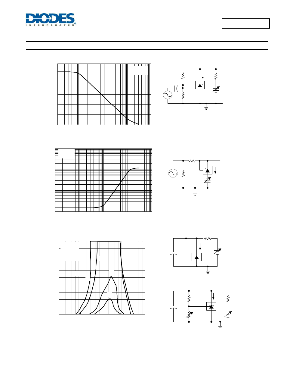
T est C ircuit for V oltage A m plification
Sm all-Signal Voltage Am plification vs Frequency
0
10
20
30
40
50
60
1K
10K
100K
1M
10M
f-Frequency-H z
A
V
-Sm
a
ll Si
gnal
Vol
tage
Am
pli
fi
c
at
ion (dB)
I
KA
=10m A
T
A
=25
o
C
+
-
I KA
GND
Output
1K
Ω
50
Ω
Test Circuit for Reference Impedance
Reference Impedance vs Frequency
0.1
1
10
100
1K
10K
100K
1M
10M
f-Frequency-Hz
∣
ZKA
∣
Refe
re
nc
e Impedance
(Ω
)
I
KA
=10mA
T =25 C
A
o
+
-
150
Ω
I KA
V
B A T T
C
L
Test C ircuit for C urve A
+
-
C
L
R 1=10K
Ω
R 2
I KA
150
Ω
V
B A T T
Test C ircuit for C urve B, C , and D
+The areas under the curves represent conditions that m ay cause the
device to oscillate. For curves B , C , and D , R 2 and V+ w ere adjusted
to establish the initial V
KA
and I
K A
conditions w ith C
L
= 0.V
B A TT
and C
L
w ere then adjusted to determ ine the ranges of stability.
S TA B ILITY B O UNDA RY CO NDITIO NS
†
0
1 0
2 0
3 0
4 0
5 0
6 0
7 0
8 0
9 0
1 0 0
0 .0 0 1
0 .0 1
0 .1
1
1 0
C
L
-L o a d C a p a cita n ce -µF
I
KA
-C
a
tho
de Cu
rr
ent
-m
A
A V
KA
=V
ref
B V
KA
=5 V
C V
KA
=1 0 V
D V
KA
=1 5 V
A
B
C
D
S ta b le
S ta b le
TA=2 5
o
C