Data sheet, Operating diagram – Diodes AM4967 User Manual
Page 10
ADJUSTABLE-SPEED SINGLE-PHASE FULL-WAVE PRE-DRIVER FOR MOTOR AM4967
Data Sheet
10
Oct. 2008 Rev. 1. 2
BCD Semiconductor Manufacturing Limited
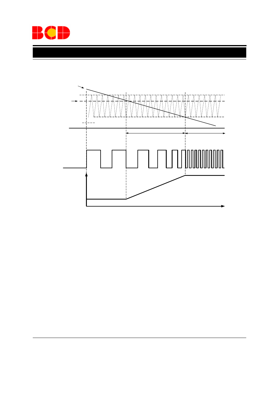
Operating Diagram
Note 3:
1. Minimum Speed Setting Mode (Stop Mode)
When fan rotate at low speed, its lowest speed is settable
by VMIN pin voltage. If not, fan motor stops.
2. Low Speed to High Speed Setting Mode
PWM control system works by comparing the voltage of
VPWM and COSC (1.0V to 3.0V). When VPWM voltage
is low, the transistors of the upper and lower side outputs
are ON. On contrary, when VPWM voltage is high, the
upper side transistors are OFF. And coil current re-circu-
lates in a lower side transistor. Therefore, as the VPWM
voltage becomes lower, output ON duty becomes large.
Sequentially, coil current increases and the motor runs at
high speed which is monitored by FG output while rota-
tion-stop state is monitored by RD output.
3. Full Speed Rotation Mode
When VPWM voltage drops to 1.0V or lower, motor fan
will run at full speed. (If the speed is not controlled,
V
PWM
=GND)
Figure 9. Operating Diagram 1 of AM4967 (Speed Control, Note 3)
VPWM Voltage
f
OSC
=30kHz (C
OSC
=220pF)
VMIN Voltage
COSC Voltage
0V
Minimum Speed Setup
Rotation (Stop Mode)
Low
Speed
PWM Adjustable
Speed
High
Speed
Full Speed
FG
ON-Duty-Large
ON-Duty-Small
3.0V
1.0V
RPM